77
6.6 Tilt lock valve operation
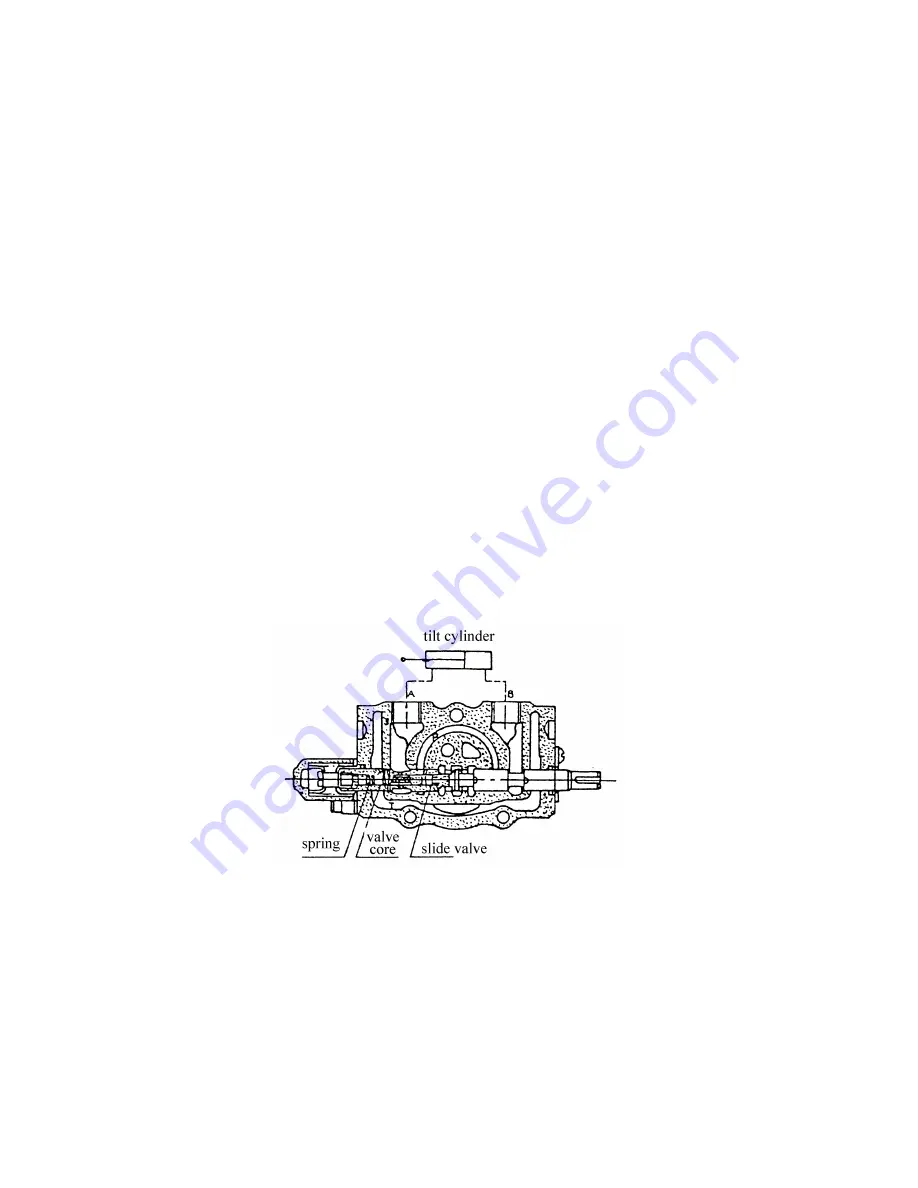
Tilt lock valve is used for preventing the shaking of the mast (because the tilt
cylinder maybe cause the inside negative pressure), at the same time, it can avoid the
danger that the mast will be tilted due to the wrong operation (hit the tilt operation staff)
when the engine is off. In traditional structure, even if the engine is off, the mast will be
pitch if someone hit the tilt operation staff. But using this new-style tilt lock valve, in spite
of the strength that push the tilt operation staff, this complexion will be not occurred. Tilt
lock valve structure, see Fig.6.9. In the picture, the port A is connect with the front of the
tilt cylinder and the port B is with the behind. When pull the tilt operation staff ( pull slide
valve), the oil that is come from the oil pump will be inpour A, and the oil that is come
from B port will be back to Oil tank. As a result, the mast will be retroverted. On the other
hand, push the tilt operation staff (push slide valve), the oil that is come from oil pump
will be inpour B, recur to the HP oil, the lock valve begin to work, then Port A can
connect with LP, the mast will be pitch. But when the engine is off, that is, have no HP oil
make the lock valve work, so Port A cannot connect with LP, and the mast will not be
pitch, at the last, the tilt cylinder will not be cause the negative pressure.
Fig. 6.9 Tilt lock valve
T: to oil tank P: to oil pump A,B: to tilt cylinder
Summary of Contents for CPCD 100
Page 1: ...Original instructions ...
Page 25: ...19 4 Lubrication system 5 Capacity chart 6 Inspections before starting ...
Page 32: ...26 Lubrication diagram ...
Page 50: ...44 Fig 2 4 Forward shift clutch Fig 2 5 Reverse shift clutch Fig 2 6 Control valve ...
Page 61: ...55 Fig 4 2 Position of brake pedal ...
Page 99: ...93 Fig 9 1 Principle diagram of electric system domestic CPCD80 100CY ...
Page 100: ...94 Fig 9 2 Principle diagram of electric system imported CPCD80 100W ...
Page 104: ...98 Fig9 5 1 Diagram of meter harness domestic CPCD80 100CY ...
Page 105: ...99 Fig9 5 2 Diagram of meter harness imported CPCD80 100W ...
Page 106: ...100 Fig9 5 3 Diagram of main harness domestic CPCD80 100CY ...
Page 107: ...101 Fig9 5 4 Diagram of main harness imported CPCD80 100W ...
Page 109: ...103 NOTE ...
Page 110: ...104 ...
Page 112: ...106 incurring any obligation ...


