100
The piston, fastened to the piston rod with spring wire is fitted with oil seals and
wearing on its outer periphery.
At the bottom of the lift cylinder there is a cut-off valve, which operates when the
high-pressure hose bursts for any reason to prevent the load from dropping abruptly.
There are steel-backed bearing and oil seal assembled on cylinder head to support
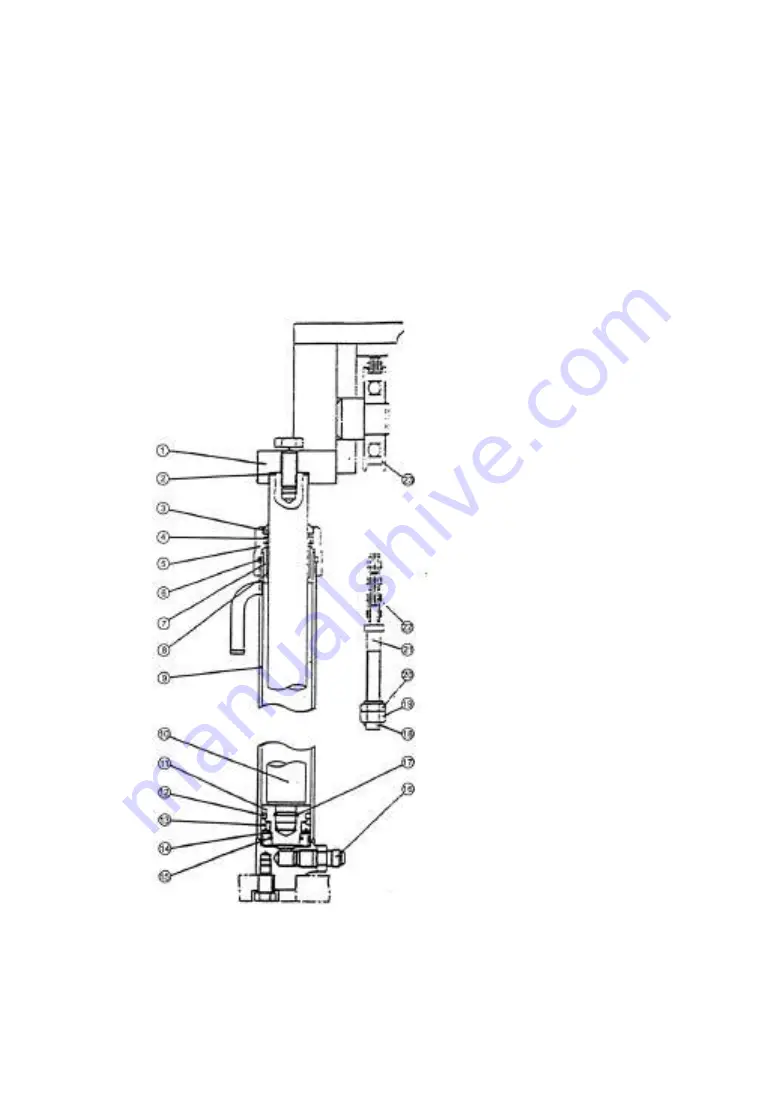
the piston rod and prevent the dust. The diagram of lift cylinder is referred to Fig7-4.
Fig.7-4 Lift cylinder
1. Upper beam
2. Adjust shim
3. Dust ring
4. Oil seal
5. Guide sleeve
6. O-ring seal
7. Cylinder head
8. Steel-backed bearing
9. Cylinder body
10. Piston rod
11. Piston
12. Oil seal, piston
13. Oil seal
14. Ring
15. Snap ring
16. Cut-off valve
17. Spring lock ring
18. Cotter pin
19. Nut, lock
20. Nut, adjustment
21. Joint
22. Chain
23. Chain wheel
Summary of Contents for CPD10
Page 1: ......
Page 6: ...1 Ⅰ External view and specification External view of electric forklift truck ...
Page 26: ...21 2 General information when operating 3 Nameplate of forklift truck 4 Lubrication system ...
Page 27: ...22 5 Capacity chart 6 Inspections before starting 7 Adjust parking brake 8 Add hydraulic oil ...
Page 33: ...28 Fig 1 2 Gear box and differential 2 3t ...
Page 34: ...29 Fig 1 3 Differential ...
Page 57: ...52 Fig 4 2 Principle of electric system DC CPD10 25 ...
Page 58: ...53 Fig 4 3 Principle of electric system DC CPD30 ...
Page 60: ...55 Fig 4 5 Principle of electric system AC ...
Page 77: ...72 4 8 Harness Fig 4 10 Harness DC CPD10 30 ...
Page 78: ...73 Fig 4 11 Harness AC CPD10J 15J ...
Page 79: ...74 Fig 4 12 Harness AC CPD20J 30J ...
Page 81: ...76 Fig 5 1 Assembly diagram of lifting motor Fig5 2 Lifting motor ...
Page 101: ...96 3 Hydraulic oil circuit ...
Page 115: ...110 Fig 8 2 Inner and outer mast 2 3t ...
Page 124: ......


