54
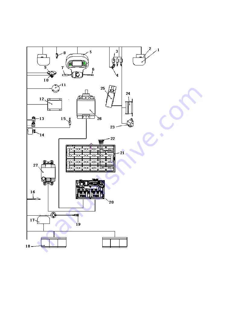
Fig.4-4 Construction of electric system (AC)
1. Head lamp
2. Front combination lamp
3. Inching switch
4. Lift potentiometer
5. Meter assy
6. Steering switch
7. Direction switch
8. Hand brake
9. Horn
10. Horn absorber
11. Foot horn switch
12. DC convertor
13. Microrelay
14. Back-up buzzer
15. Foot brake switch
16. Seat switch
17. Warning lamp
18. Rear combination lamp
19. Steering potentiometer
20. Controller assy
21. Battery assy
22. Socket and connector
23. Flasher
24. Fuse box
25. Accelerator
26. Traction motor
27. Lifting motor
Summary of Contents for CPD10
Page 1: ......
Page 6: ...1 Ⅰ External view and specification External view of electric forklift truck ...
Page 26: ...21 2 General information when operating 3 Nameplate of forklift truck 4 Lubrication system ...
Page 27: ...22 5 Capacity chart 6 Inspections before starting 7 Adjust parking brake 8 Add hydraulic oil ...
Page 33: ...28 Fig 1 2 Gear box and differential 2 3t ...
Page 34: ...29 Fig 1 3 Differential ...
Page 57: ...52 Fig 4 2 Principle of electric system DC CPD10 25 ...
Page 58: ...53 Fig 4 3 Principle of electric system DC CPD30 ...
Page 60: ...55 Fig 4 5 Principle of electric system AC ...
Page 77: ...72 4 8 Harness Fig 4 10 Harness DC CPD10 30 ...
Page 78: ...73 Fig 4 11 Harness AC CPD10J 15J ...
Page 79: ...74 Fig 4 12 Harness AC CPD20J 30J ...
Page 81: ...76 Fig 5 1 Assembly diagram of lifting motor Fig5 2 Lifting motor ...
Page 101: ...96 3 Hydraulic oil circuit ...
Page 115: ...110 Fig 8 2 Inner and outer mast 2 3t ...
Page 124: ......


