35
Fuse replacement
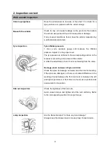
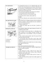
If a lamp does not come on or an electrical device does not
function, the corresponding fuse may be blown. Check the fuse
for each device. The lighting location on the fuse box is blown
fuse when electrified. The fuse box is located in the front left as
seen from the opened engine hood.
The fuse check and replacement procedures are as follows:
1. Set the ignition switch to the OFF position.
2. Remove the fuse box cover and check the fuse.
3. If the fuse is blown, replace it with a spare fuse.
Caution:
Use the fuse having the same capacity as that of the installed
one.
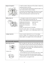
Air purge of the fuel system
When fuel has been completely depleted or when maintenance
has been performed on the fuel system, be sure to perform air
purge in the following sequence.
1. Open the engine hood.
2. Operate the priming pump up and down to perform air
bleeding.
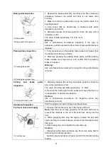
Draining the sedimenter
(1) Priming pump
(2) Drain plug
(3) Drain hose
The sedimenter separates the water contained in the fuel. It is
integrated with the fuel filter.
If the sedimenter warning lamp comes on, immediately drain
water according to the following procedure because the
accumulated water in the sedimenter is above the specified
level:
1. Place a water receiving container under the open end of the
drain hose under the fuse filter.
2. Turn around the drain cock a time or two to loose it and
operate the priming pump up and down to drain the water in the
sedimenter.
3. When fuel starts to flow out after the end of water draining,
firmly tighten the drain cock.
Caution:
Wipe the fuel clearly from the adjacent area.
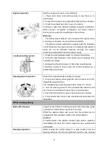
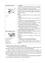
Cleaning the radiator fin
Clean the radiator and radiator fin, if debris is trapped therein,
this may cause over-heating.
Caution:
.
After stopping the engine, confirm that the engine has
sufficiently cooled down before cleaning. Taking inadequate
precautions may result in burns.
.
When cleaning the radiator fin, take care not to cause it to
become deformed.
.
When performing cleaning, always wear safety goggles and
dust mask.
Summary of Contents for F Series
Page 1: ...1...
Page 7: ...1 About F series forklift truck 1 External view and technical parameter Fig1 1 External view...
Page 95: ...89 Fig8 3 1 Diagram of harness 4JG2 engine...
Page 96: ...90 Fig8 3 2 Diagram of harness Dachai 498 engine...
Page 97: ...91 Fig8 3 3 Diagram of harness Xinchai 498engine...
Page 98: ...92 Fig8 3 4 Diagram of harness Yanmar 4TNE98 engine...
Page 99: ...93 NOTE...
Page 100: ...94...
Page 102: ......

