Installation & Operating Instructions
Building Automation Products, Inc., 750 North Royal Avenue, Gays Mills, WI 54631 USA
Tel:+1-608-735-4800 • Fax+1-608-735-4804 • E-mail:sales@bapihvac.com • Web:www.bapihvac.com
rev. 08/15/23
50387_Wireless_BLE_Gateway
2 of 4
Wireless Bluetooth Low Energy Gateway
Green “Power” LED
Slow Blink
= Normal Operation. Gateway is connected to the Wi-Fi network.
Fast Blink
= Gateway is in SoftAP mode waiting for you to complete the connection
process.
Constant On
= Gateway is locked up, requiring a physical reset by unplugging and
then plugging back in the Micro USB power supply or PoE source.
Blue “Bluetooth” LED
Periodic Blink
= Data transmission received from a paired sensor.
Fast Blink
= Gateway is in pairing mode and waiting to be paired with a sensor.
Amber “Wi-Fi” LED
Slow Blink
= Gateway is not connected to the Wi-Fi network.
Fast Blink
= Gateway is attempting to connect to the Wi-Fi network.
(Green “Power” LED will be on solid during this time.)
Note: The gateway shuts off the Bluetooth Low Energy radio when a Wi-Fi connection is lost, forcing the sensors into
memory mode until the connection is re-established. (See “Sensor Memory Mode” on pg 3 for more information.)
Pairing Sensors with the Gateway
1. Select the sensor that you wish to pair to
the gateway. Apply power to the sensor.
See its manual for detailed instructions.
2. Press and hold the “Service” button on the
gateway until the blue “Bluetooth” LED
begins to flash (about 3 seconds). Then
release the “Service” button to enter pairing
mode. NOTE: When in pairing mode, the
blue “Bluetooth” LED will continue to flash
providing the user a 20 second window to
pair the sensor with the gateway.
3. Press the “Service” button on the sensor to
pair it with the gateway. When the sensor
is successfully paired, the sensor will flash
its green “Service” LED 3 times. At that
point, the gateway will leave pairing mode
and the blue “Bluetooth” LED will go out.
The blue “Bluetooth” LED will then flash
each time a sensor communicates with
the gateway. Repeat this process for all
sensors. The gateway and sensor pairings
are now complete.
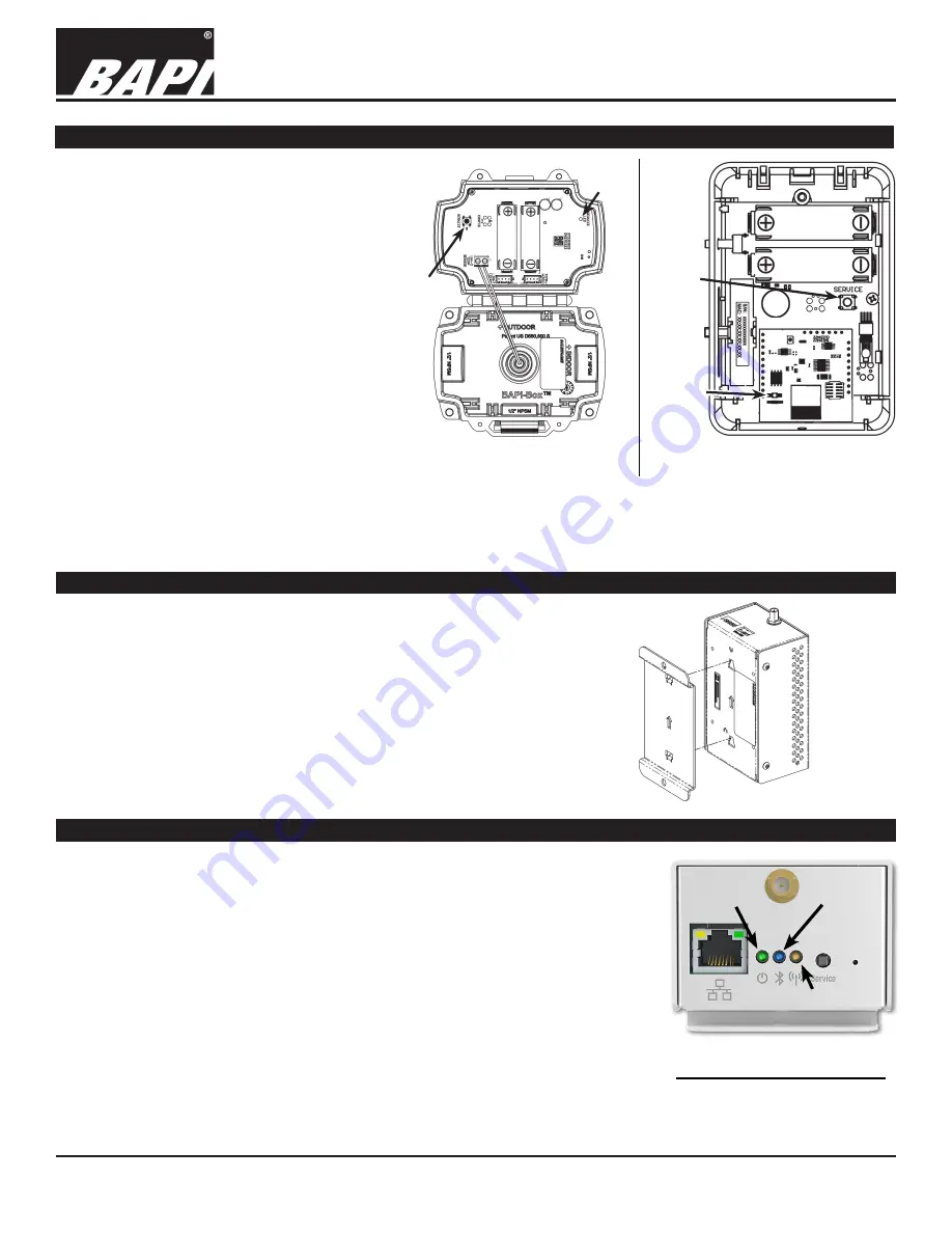
Fig. 4:
BAPI-Box Sensor
Service Button and LED
Service
LED
Service
Button
Service
LED
Service
Button
Fig. 5:
BAPI-Stat “Quantum”
Sensor Service Button and LED
The figures above are shown for reference. Refer to the
instructions document for your specific sensor for the location
of the “Service” button and “Service” LED.
The gateway includes a removable keyhole type base plate that allows you
to mount the gateway in a vertical or horizontal position. Remove the base
plate from the gateway and use it to mark the mounting hole locations on
your mounting surface. If mounting in a vertical position, ensure that the
arrows in the base plate and gateway are pointing up. Mount the base
plate to the surface. Then slide the gateway on to the base plate.
NOTE ON ANTENNA:
The unit must use the supplied antennas. Do not
replace the antennas with other antennas. Using antennas other than the
ones provided by BAPI may violate FCC regulations.
Mounting
Green
“Power”
LED
Blue
“Bluetooth”
LED
Amber “Wi-Fi”
LED
Fig. 7:
Gateway LEDs
LED Operation
Fig. 6:
Gateway
mounting


