Installation & Operating Instructions
Building Automation Products, Inc., 750 North Royal Avenue, Gays Mills, WI 54631 USA
Tel:+1-608-735-4800 • Fax+1-608-735-4804 • E-mail:sales@bapihvac.com • Web:www.bapihvac.com
Specifications subject to change without notice.
rev. 01/25/18
39021_RCV_900_BACnet
2 of 9
900MHz BACnet Gateway/Receiver
Mounting and Termination
MOUNTING
Attach the antenna to the Gateway and position the
Gateway within range of the sensors (275 feet line of sight
range max). To achieve maximum range, do not mount the
Gateway behind any objects or inside a metal enclosure.
NOTE: For maximum range if the Gateway is mounted to a
wall, fold the antenna to the vertical position.
Terminate the unit as described below and then verify
communication as described in the “Gateway Network
Setup” section. After verifying communication, permanently
mount the Gateway and re-verify communication between
the sensors and Gateway.
TERMINATION
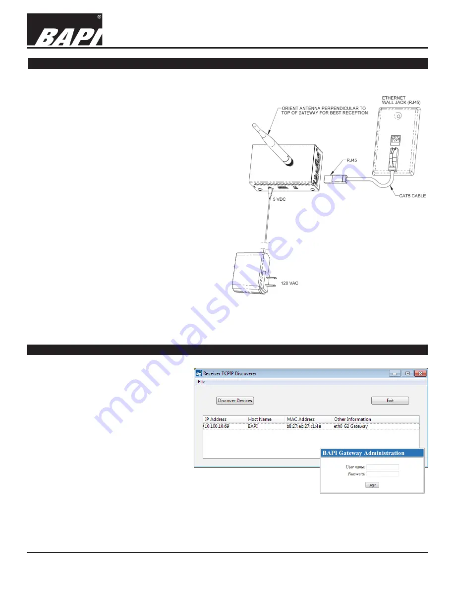
Figure 2 shows the power, antenna and Ethernet
connections for the Gateway. The Gateway is powered by
a plug-in 5VDC power supply provided with the unit. The
plug is inserted into the “5 VDC” jack. It is recommended
to make a proper ethernet connection first before applying
power to the Gateway.
Connect the supplied CAT5 cable to the Ethernet wall jack
and to the Gateway Ethernet port.
When the Ethernet cable is connected, the yellow LED to
the left of the Ethernet jack will illuminate, indicating that
the network is linked. The green LED on the right of the
Ethernet jack will begin blinking, indicating network activity.
If either LED stays dark, then there may be a problem with
the power to the unit or the Ethernet connection.
Fig. 2:
900MHz BACnet
Gateway/Receiver
Termination
Gateway Network Setup
Fig. 3:
Gateway TCP/IP Discoverer
(above) and Login Screens
TCP/IP DISCOVERER UTILITY
Download and install the WAM Discoverer
Utility from the BAPI website at
www.bapihvac.com. Click on the “Wireless”
Icon, then “WAM - Wireless Asset Monitoring”,
then “WAM Local”, then click on the link “Click
here to download WAM Gateway Utilities”
which will download the utilities.
Running the utility finds the Gateway on
the network and displays the MAC and IP
addresses of the unit.
The Discoverer screen will show all Gateways
that are currently available on the network.
Click on the assigned Gateway IP address that
is displayed on the Discoverer utility to launch
the Gateway Administration “Login” screen.
Enter user name “admin1” and password
“bapi1” to navigate to the Gateway
Configuration screen. (Fig. 3)


