


7
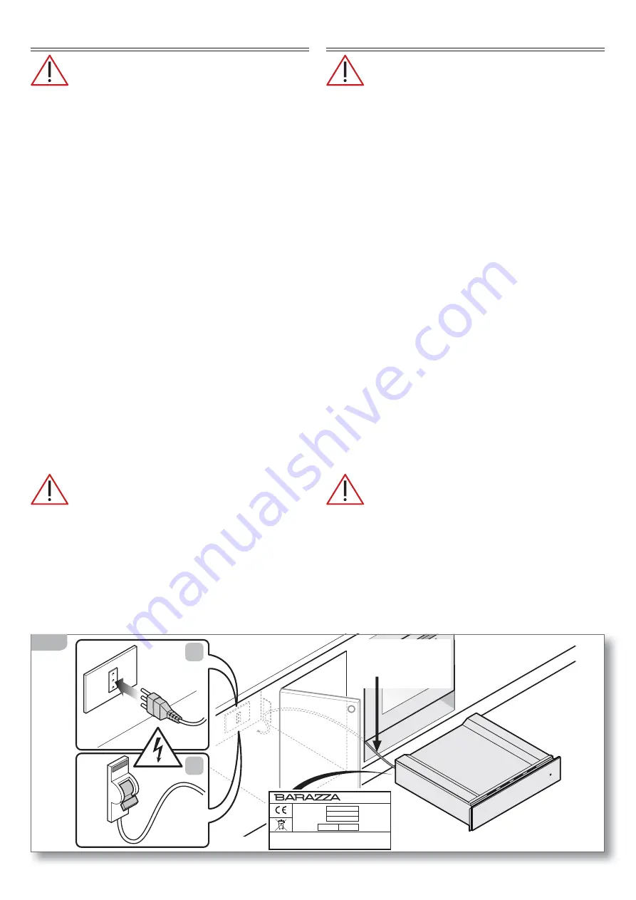
CONNECTION TO THE POWER MAINS
Before making the connection, make certain
that the voltage and frequency indicated on the
data plate match those of the power supply system.
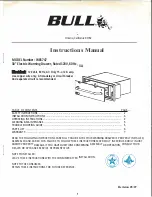
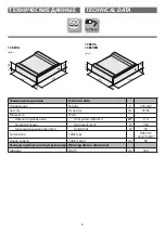
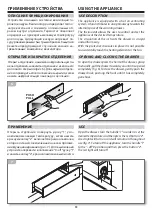
The warming drawer is supplied with a 90 cm-long power
cord (H05VV-2) (fig. 2a).
Connect the cable directly to the electricity supply
(fig.2b), which must be made by an authorized person
in accordance with current regulations in the country
where the appliance is installed. The installation must
include a means for disconnection from the supply hav-
ing an air gap contact separation in all active conduc-
tors that allows complete disconnection in category III
overvoltage condictions. The isolating switch should be
sized according to the load on the data label and should
comply with current regulations. If the supply cord is
damaged , it must be replaced by the manufacturer or
its service agent or a similarty qualified person in order
to avoid hazard.
The isolating switch must be located in a position
which is accessible even after the appliance is in-
stalled.
If the appliance is installed together with a hob, the
connection of the two appliances must be independ-
ent for electrical safety reasons.
The power cord must
NOT
:
- be crushed or rolled up;
- come into contact with any type of liquid, sharp or hot
objects or corrosive substances;
- reach, at any point, a temperature which is 50°C higher
than the room temperature;
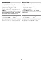
- be replaced with a different type of cable (see “Technical data”
on page 4) or with a cable which is not up to standard;
- be lengthened with extensions.
ЭЛЕКТРИЧЕСКОЕ ПОДКЛЮЧЕНИЕ
Перед подсоединением убедиться, что
напряжение и частота, указанные на табличке
с паспортными характеристиками, соответству-
ют характеристикам системы питания.
Прибор для подогрева пищи поставляется в ком-
плекте с силовым кабелем (H05VV-2) длиной 90 cм,
на котором должна устанавливаться вилка, выдер-
живающая 10 A
(рис. 2a)
. В качестве альтернативы
можно подсоединить кабель непосредственно к
распределительной сети (рис. 2b): операция должна
производиться квалифицированным персоналом в
соответствии с нормативом, действующим в стране
монтажа. Системой должно быть предусмотрено
устройство, обеспечивающее отсоединение от сети,
с расстоянием между контактами, обеспечивающим
полное отсоединение при условиях категории избы-
точного напряжения III. Выключатель должен быть
соразмерен в соответствии с нагрузкой, указанной
на паспортной табличке, и должен соответствовать
действующим нормативам.
В случае повреждения силового кабеля, он подле-
жит замене Изготовителем, его Сервисной Службой,
или подобным квалифицированным персоналом
таким образом, чтобы предупредить любые риски.
Как розетка тока, так и всеполюсный выключа-
тель должны соответствовать и размещаться в
положении, доступном даже при встроенной
приборе. Если прибор устанавливается вместе
с варочной поверхностью, подсоединение двух
устройств должно быть независимым по при-
чинам электрической безопасности.
Силовой кабель
НЕ
должен:
- быть сдавленным или закрученным;
- находиться в контакте с любыми жидкостями,
режущими или горячими предметами и корро-
зионными веществами;
- достигать в какой-либо точке температуры, превы-
шающей на 50°C температуру окружающей среды;
- заменяться на кабель другого типа
(см. “Техниче-
ские данные» стр. 4)
или на несоответствующий;
- быть удлиненным посредством удлинителей.
7
10A
B
A
Mod.
Art.
N°
...V ...Hz
...Kw
Questo apparecchio deve essere installato conformemente
alle norme in vigore. Consultare il libretto istruzioni prima
di installare e usare l’apparecchio
F.lli Barazza S.r.l
MADE IN ITALY
H05VV-2
3x0,75mm
2
90 cm
2
Summary of Contents for 1CEEVEN
Page 1: ...0 1CEEVG 1CEEVS 1CEEVEN 1CEEVG 1CEEVS 1CEEVEN...
Page 17: ......
Page 18: ...18 Note...
Page 19: ......