13
Safety, Assembly & Instruction Manual 13
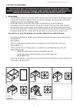
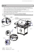
figure 4
figure 3
figure 5
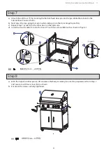
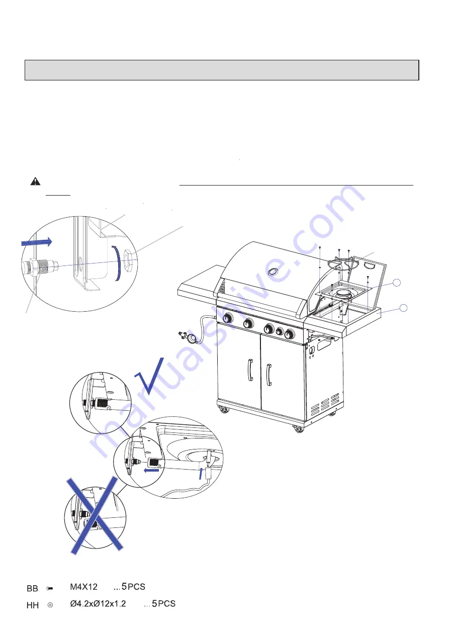
Step 10
a) Attach the side burner valve onto the side valve support bracket located on the Right Side Shelf (G) as in
figure 3. Use the locking nut pre-assembled to the side burner valve nozzle to do this. Tighten the locking
nut with an adjustable spanner to secure the valve nozzle firmly onto the bracket.
b) Open the side burner lid and place the Side Burner Assembly (H) into the Right Side Shelf (G).
Ensure the valve nozzle enters into the burner pipe as in figure 4.
c) Align the holes on the Side Burner Assembly (H) with the holes in the Right Side Shelf (G) and secure it with
five screws (BB) and five washers (HH) as in figure 5.
d) Ensure the Trivet is properly located into the top of the Side Burner Assembly (H).
e) Connect the side burner ignition cable by inserting it onto the electrode (figure 4).
Make certain the connection is secure. Recheck that the burner pipe is engaged onto the side burner valve
nozzle!
mm
mm
Locking Nut
(Pre-installed on the side burner nozzle. Remove from the
nozzle, then use this nut to fix the nozzle to the bracket.)
support
bracket
Trivet
G
H
Side Burner
Valve Nozzle


