14
2.
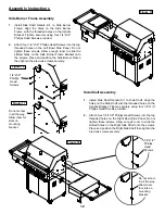
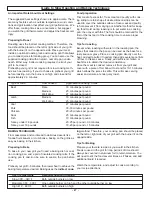
Evenly space the Stainless Steel Cooking Grids on the
ledge above the Flame Tamers.
3.
Place the Secondary Cooking Rack into the holes on
the upper left and upper right of the back burner frame
with the bottom resting in the slots on either side of the
grill bowl.
Connecting A Liquid Propane (LP) Gas Tank To
Your Grill
1.
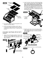
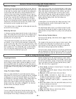
Attach LP Hose & Regulator assembly to the Rear Gas
Manifold as shown in
Figure 24
. Ensure that connec-
tions are gas tight (Do NOT use Pipe Sealant on these
flare connections).
2.
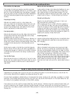
Open the left door. Pull out the LPG tank drawer (these
are not supplied with Natural Gas models).
Note:-Tank
drawer must be installed into the cart by the con-
sumer as per the instructions supplied with drawer
kit.
Place the 20 Ib cylinder with foot ring into the hole
in the drawer. See
Figure 25.
Make sure the tank valve
is in the OFF position. Make sure the gas tank is in the
upright position. Use the 5/16” x 90mm wing bolt provid-
ed to secure gas tank.
3.
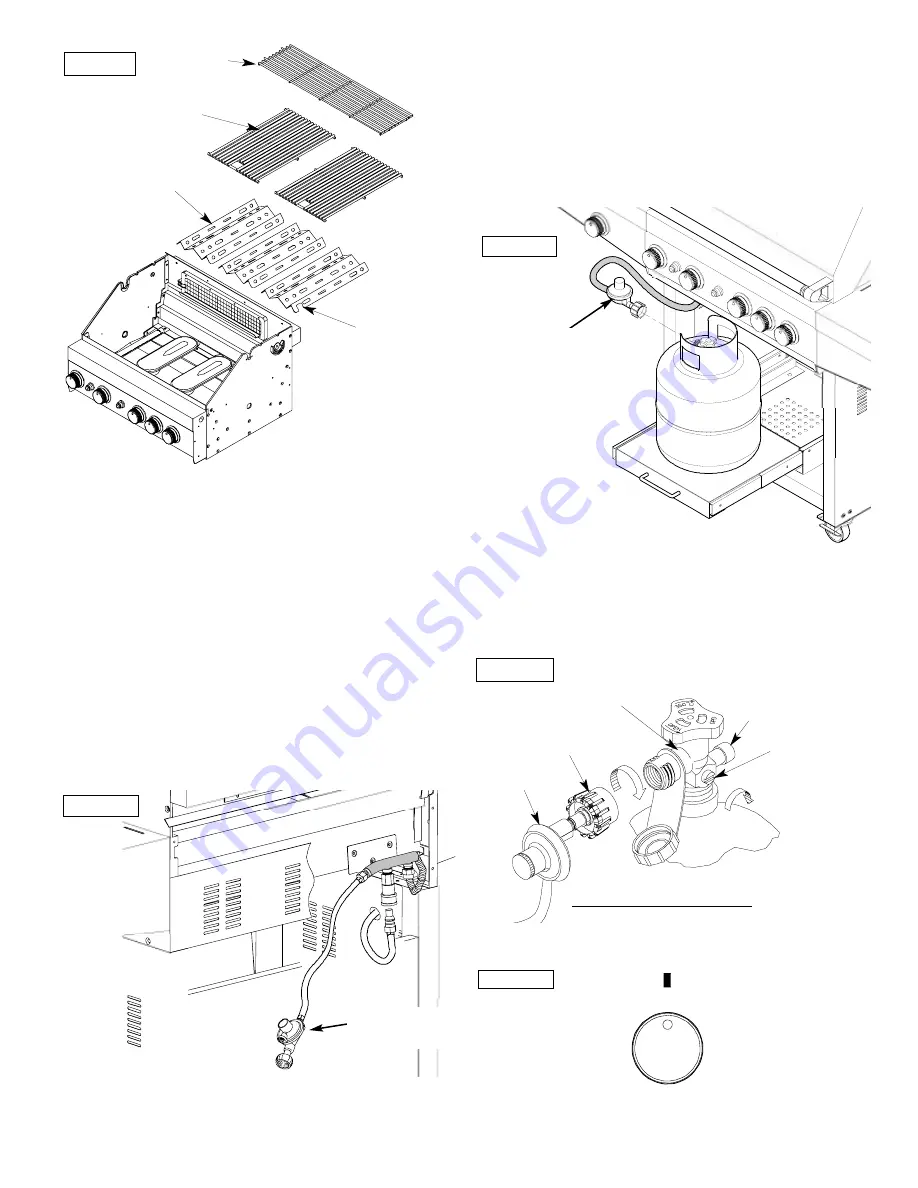
Check the tank valve to ensure it has proper external
mating threads to fit the hose & regulator assembly pro-
vided. See
Figure 26.
(Type 1 connection per ANSI
Z21.58a-1998).
4.
Make sure all burner valves are in the OFF position.
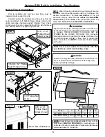
SECONDARY
COOKING
RACK
COOKING
GRID
S/S FLAME
TAMER
S/S FLAME
TAMER WITH
CUTOUT FOR
LIGHTING TUBE
Figure 23
LP Regulator &
Hose assembly
Figure 24
LP Regulator
& Hose
assembly
Figure 25
Figure 26
QCC-1 CYLINDER VALVE
BLACK COUPLING NUT
PRESSURE
RELIEF VALVE
BLEED-OFF
VALVE
Turn Clockwise
to Reseal
QCC-1 OPD Connection
Turn Clockwise to connect
REGULATOR
OFF
Figure 27

