6. GUI orientation
Image 6-56
Once the two keyframes are de
fi
ned, the PIP can move between the two positions by pressing the green arrow buttons. The rate
for the movement is adjusted by changing the number in the corresponding box.
Any of the two keyframes can be deleted when the keyframe is highlighted and by pressing the “Delete KF” button.
The red LED in the keyframe button indicates the current position of the PIP.
Layer adjustment panel > Main adjustment
The Main adjustment panel is variable according the Layer type.
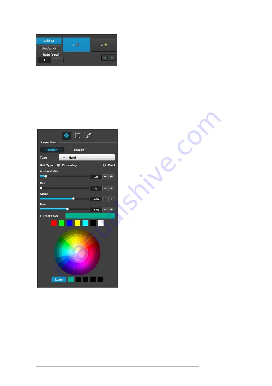
Layer type = PIP (Border Tab)
:
This menu allows users to adjust the PIP borders.
•
Borders are enabled by selecting the type of to apply. Six
types are available:
-
Hard
-
Soft
-
Halo
-
Halo-in
-
Halo-out
•
Border width
and color are selected by adjusting the
corresponding sliders or entering a
fi
gure in the adjacent
edit boxes. The
border width
can be entered either in
Percentage of the vertical size or in pixels.
•
The selected color is shown in the
Current Color
bar. The
color can also be stored by clicking in one of the square
boxes at the bottom of the menu next to the Learn button.
These boxes are quick shortcuts to select that color for
the Border.
•
Another way to specify a color is to click on the
Color
wheel
. The slider values will change accordingly as the
mouse moves around the color wheel.
•
Learn
: The “Learn” button in the bottom is a way to store
custom colors to be used for later. The way to use this
area is to:
a) Pick a color to save, using color wheel or the R/G/B
adjustments.
b) Click Learn button.
c) Click any one of the buttons on the right.
d) The color that was picked is now stored in this button.
Layer type = PIP (Shadow Tab)
:
The Shadow Menu enables the user to place a shadow behind a PIP.
122
R5905948 E2 12/12/2014
Summary of Contents for Event Master E2
Page 1: ...E2 User s guide R5905948 00 12 12 2014...
Page 8: ...Table of contents 4 R5905948 E2 12 12 2014...
Page 16: ...2 Safety 12 R5905948 E2 12 12 2014...
Page 32: ...3 General 28 R5905948 E2 12 12 2014...
Page 82: ...6 GUI orientation Image 6 8 78 R5905948 E2 12 12 2014...
Page 94: ...6 GUI orientation Image 6 20 90 R5905948 E2 12 12 2014...
Page 115: ...6 GUI orientation Image 6 37 Thumbnail view Image 6 38 R5905948 E2 12 12 2014 111...
Page 186: ...7 System Setup 182 R5905948 E2 12 12 2014...
Page 192: ...8 Updating firmware 188 R5905948 E2 12 12 2014...
Page 196: ...9 General operation example Image 9 3 192 R5905948 E2 12 12 2014...
Page 213: ...9 General operation example Image 9 25 R5905948 E2 12 12 2014 209...
Page 216: ...9 General operation example 212 R5905948 E2 12 12 2014...
Page 220: ...10 Maintenance 10 2 Process Overview Flow chart Image 10 2 216 R5905948 E2 12 12 2014...
Page 281: ...10 Maintenance Disregard the heatsink from the spare kit R5905948 E2 12 12 2014 277...
Page 282: ...10 Maintenance 278 R5905948 E2 12 12 2014...
Page 288: ...11 Environmental information 284 R5905948 E2 12 12 2014...
Page 298: ...B Remote Control Protocol 294 R5905948 E2 12 12 2014...
Page 299: ...C Troubleshooting C TROUBLESHOOTING R5905948 E2 12 12 2014 295...
Page 300: ...C Troubleshooting 296 R5905948 E2 12 12 2014...