


9. General operation example
9.4
Con
fi
guration Menu
Overview
Here, we de
fi
ne E2 components by adding inputs, backgrounds, outputs and destinations.
C1: Initial Setup
1. When you connect to an actual unit, instead of working of
fl
ine, the software should connect automatically. The unit is listed in the
System con
fi
guration page under the “Discovered” tab with the button on turning green.
2. Drop the E2 from the device area into the middle diagram area.
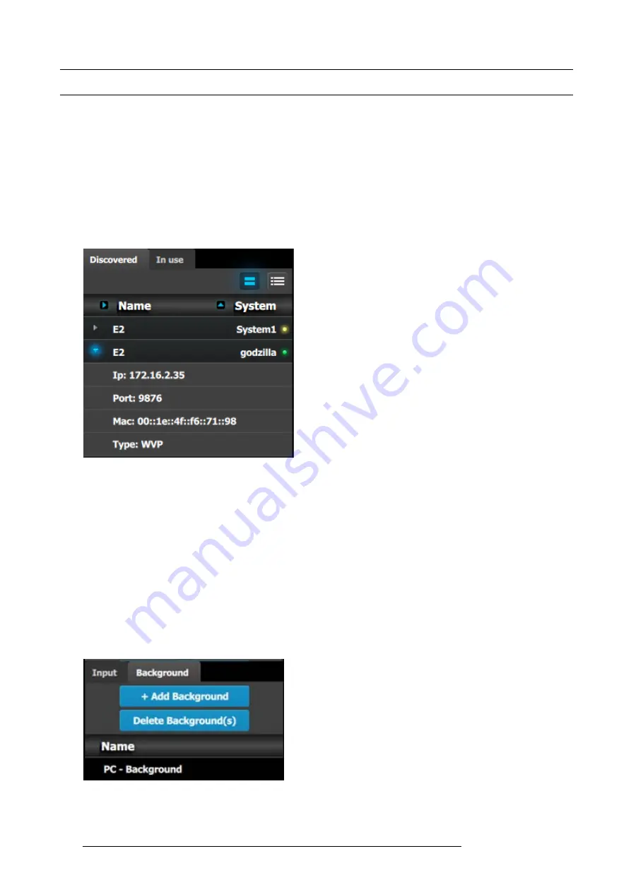
3. If multiple units are connected to the PC, the green LEDs next to the system name will turn green. You can assign a unique name
to each unit. In this application we will connect to only one unit and assign the name “Godzilla” to it. For online operations, you
can con
fi
rm that you are connected to the right unit by clicking the arrow in front of E2 to reveal the unit’s IP address. Verify that
this address is the same as the address listed on the unit’s front panel on the top status menu
Image 9-5
Note:
If the unit doesn’t connect automatically to the PC, you can type the PC’s IP address in the
fi
eld under “Manual Connect”.
4. For this application we will leave the default setting for Native rate: 59.94, Mode: 2K and Genlock: OFF.
C2: Add Background
1. Click on the “Background” tab to select the input that will be assigned as a background.
2. Click on the
+Add Background
blue button to enter the Add mode.
3. Click on the top DVI connector of slot 6 to select the input to de
fi
ne as background.
4. Click on the bottom DVI connector of slot 6 to select the input to de
fi
ne as background. We need to do this twice because the
background comes from a dual-head DVI card.
5. Click on the
Done Adding
button to exit the Add mode.
6. Double click on
Background1
in the Name list to edit the name.
7. When the area turns blue, click the eraser icon to clear the
fi
eld.
8. Type a new name, “PC-Background”. Hit enter when done.
Image 9-6
194
R5905948 E2 12/12/2014
Summary of Contents for Event Master E2
Page 1: ...E2 User s guide R5905948 00 12 12 2014...
Page 8: ...Table of contents 4 R5905948 E2 12 12 2014...
Page 16: ...2 Safety 12 R5905948 E2 12 12 2014...
Page 32: ...3 General 28 R5905948 E2 12 12 2014...
Page 82: ...6 GUI orientation Image 6 8 78 R5905948 E2 12 12 2014...
Page 94: ...6 GUI orientation Image 6 20 90 R5905948 E2 12 12 2014...
Page 115: ...6 GUI orientation Image 6 37 Thumbnail view Image 6 38 R5905948 E2 12 12 2014 111...
Page 186: ...7 System Setup 182 R5905948 E2 12 12 2014...
Page 192: ...8 Updating firmware 188 R5905948 E2 12 12 2014...
Page 196: ...9 General operation example Image 9 3 192 R5905948 E2 12 12 2014...
Page 213: ...9 General operation example Image 9 25 R5905948 E2 12 12 2014 209...
Page 216: ...9 General operation example 212 R5905948 E2 12 12 2014...
Page 220: ...10 Maintenance 10 2 Process Overview Flow chart Image 10 2 216 R5905948 E2 12 12 2014...
Page 281: ...10 Maintenance Disregard the heatsink from the spare kit R5905948 E2 12 12 2014 277...
Page 282: ...10 Maintenance 278 R5905948 E2 12 12 2014...
Page 288: ...11 Environmental information 284 R5905948 E2 12 12 2014...
Page 298: ...B Remote Control Protocol 294 R5905948 E2 12 12 2014...
Page 299: ...C Troubleshooting C TROUBLESHOOTING R5905948 E2 12 12 2014 295...
Page 300: ...C Troubleshooting 296 R5905948 E2 12 12 2014...


