5. Front Panel Menu orientation
5.8
System menu > USB device (Backup/Restore)
General
The front panel of the E2 contains a USB port that you can use to connect a
fl
ash drive to the E2.
The
fl
ash drive must be formatted to use the FAT32
fi
le system. For formatting instructions, refer to section
Formatting the
fl
ash drive in the chapter "Upgrading
rmware using the USB port", page 184.
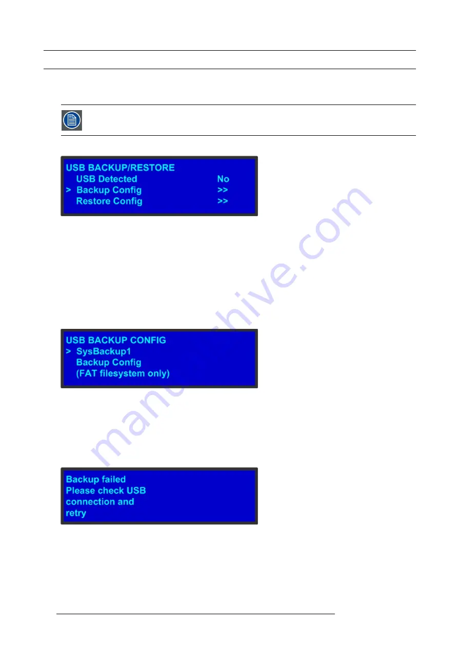
The following illustration shows the
USB Backup/Restore
submenu, which you access from the
System
menu.
Image 5-9
USB submenu
Using this menu, you can:
•
Detect the presence of a USB device.
•
Backup and restore E2 con
fi
guration
fi
les. When you connect a
fl
ash drive to the E2, the E2 creates a directory titled
E2Backup
on the drive. All con
fi
guration
fi
les are saved to this directory.
How to back up a con
fi
guration
fi
le to a
fl
ash drive?
1. Insert a formatted
fl
ash drive in the E2’s front-panel USB port.
2. From the
System
menu, scroll to the
USB Backup/Restore
submenu. Select
Backup Con
fi
g
.
The
USB Backup Con
fi
g
submenu appears, as shown in the following illustration. The navigation cursor appears at the default
name for the
fi
rst backup
fi
le.
Image 5-10
USB Backup Con
fi
g submenu
3. If you wish to change the default name of the backup con
fi
guration, press
SEL
. Use the
ADJUST
knob to change the name, as
described in section "Using menu system", page 48. Press
SEL
again when you complete the name change.
4. Scroll to
Backup Con
fi
g
and press
SEL
.
A con
fi
rmation message appears when the backup is complete.
If the backup operation fails, the message shown in the following illustration appears. Check that the
fl
ash drive is properly
formatted and installed, and try again.
Image 5-11
How to restore a system con
fi
guration
fi
le that is stored on a
fl
ash drive?
1. Insert a formatted
fl
ash drive in the E2’s front-panel USB port.
2. From the
System
menu, scroll to the
USB Backup/Restore
submenu. Select
Restore Con
fi
g
.
54
R5905948 E2 12/12/2014
Summary of Contents for Event Master E2
Page 1: ...E2 User s guide R5905948 00 12 12 2014...
Page 8: ...Table of contents 4 R5905948 E2 12 12 2014...
Page 16: ...2 Safety 12 R5905948 E2 12 12 2014...
Page 32: ...3 General 28 R5905948 E2 12 12 2014...
Page 82: ...6 GUI orientation Image 6 8 78 R5905948 E2 12 12 2014...
Page 94: ...6 GUI orientation Image 6 20 90 R5905948 E2 12 12 2014...
Page 115: ...6 GUI orientation Image 6 37 Thumbnail view Image 6 38 R5905948 E2 12 12 2014 111...
Page 186: ...7 System Setup 182 R5905948 E2 12 12 2014...
Page 192: ...8 Updating firmware 188 R5905948 E2 12 12 2014...
Page 196: ...9 General operation example Image 9 3 192 R5905948 E2 12 12 2014...
Page 213: ...9 General operation example Image 9 25 R5905948 E2 12 12 2014 209...
Page 216: ...9 General operation example 212 R5905948 E2 12 12 2014...
Page 220: ...10 Maintenance 10 2 Process Overview Flow chart Image 10 2 216 R5905948 E2 12 12 2014...
Page 281: ...10 Maintenance Disregard the heatsink from the spare kit R5905948 E2 12 12 2014 277...
Page 282: ...10 Maintenance 278 R5905948 E2 12 12 2014...
Page 288: ...11 Environmental information 284 R5905948 E2 12 12 2014...
Page 298: ...B Remote Control Protocol 294 R5905948 E2 12 12 2014...
Page 299: ...C Troubleshooting C TROUBLESHOOTING R5905948 E2 12 12 2014 295...
Page 300: ...C Troubleshooting 296 R5905948 E2 12 12 2014...


