6. GUI orientation
6.11 Con
fi
guration Menu > Adjustment area
General
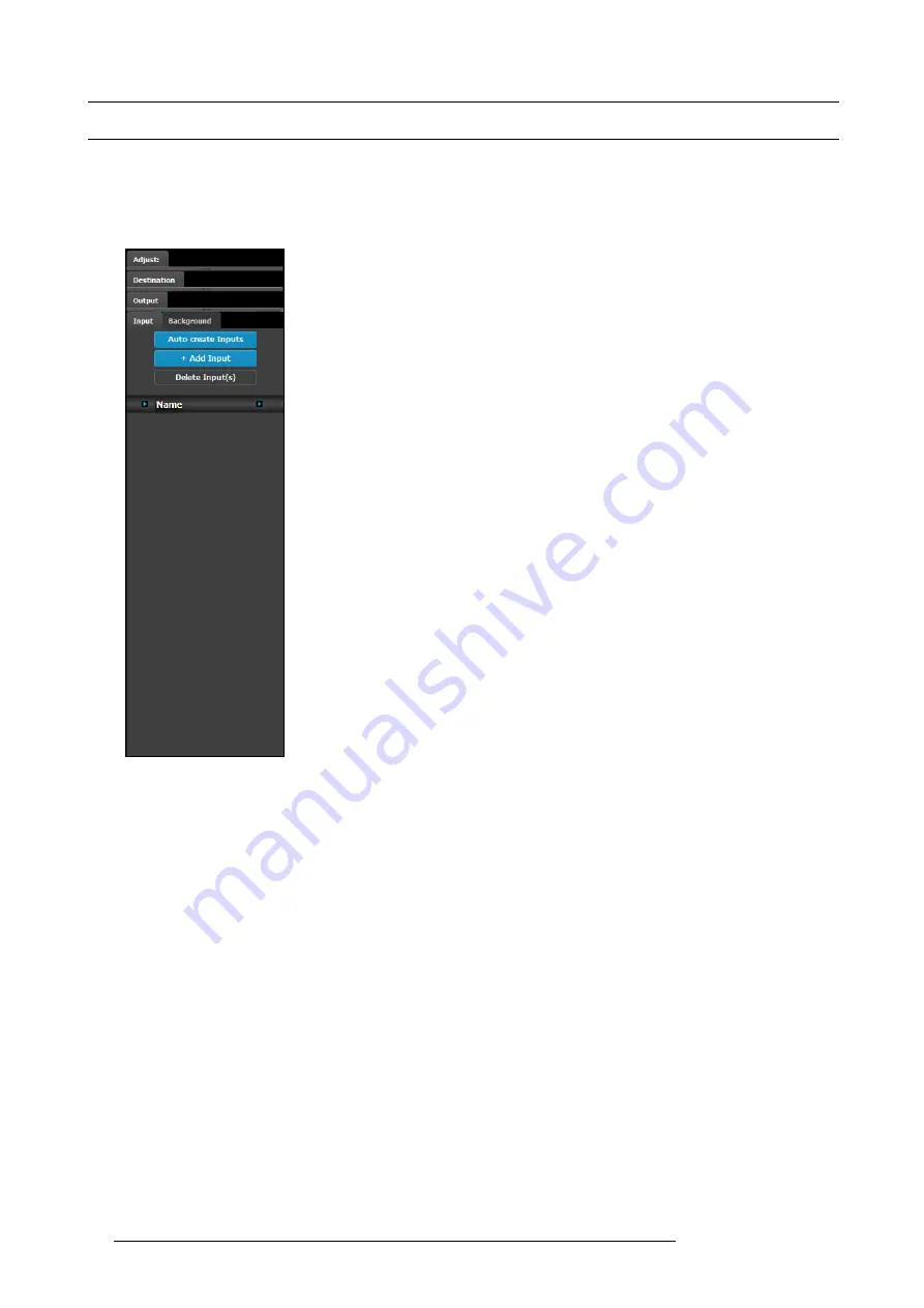
Situated on the right hand side of the screen is the Adjustment area. In this area the user can de
fi
ne and adjust unit speci
fi
c param-
eters, inputs, backgrounds, outputs and destination affected to the selected system.
Description
There are 4 tabs in this area:
•
Input
: this tab provides a list of all the created inputs. Here the user can create
new entries by associating them with input connectors. It is also in this tab that
the user can delete unused or obsolete inputs.
•
Background
: provides a list of backgrounds of the selected system. Similarly to
inputs, the user can add and remove Backgrounds from the system.
•
Output
: the user can add or remove outputs in this list.
•
Destination
: a destination is a location where the user can route the output of E2
(screens, multiple screens, monitors etc.). The user could assign the outputs that
are created in the previous tab to Destinations, and deleted unused or obsolete
Destinations.
Always on top:
•
Adjustment
: in this tab the user performs adjustments available for the selected
item (device, input, background, output, destination). The content of this tab
varies depending on the selected item. Access to this area is achieved from the
System diagram area
(click on device or on a destination) or in one of the tabs of
the
Adjustment area
(input, background, output, destination) .
The following sections describe how to perform the con
fi
guration of each part of the system in detail:
•
guration Menu > Adjustment > Unit Con
•
guration Menu > Adjustment > Input Con
•
guration Menu > Adjustment > Background Con
•
guration Menu > Adjustment > Output Con
•
guration Menu > Adjustment > Destination Con
82
R5905948 E2 12/12/2014
Summary of Contents for Event Master E2
Page 1: ...E2 User s guide R5905948 00 12 12 2014...
Page 8: ...Table of contents 4 R5905948 E2 12 12 2014...
Page 16: ...2 Safety 12 R5905948 E2 12 12 2014...
Page 32: ...3 General 28 R5905948 E2 12 12 2014...
Page 82: ...6 GUI orientation Image 6 8 78 R5905948 E2 12 12 2014...
Page 94: ...6 GUI orientation Image 6 20 90 R5905948 E2 12 12 2014...
Page 115: ...6 GUI orientation Image 6 37 Thumbnail view Image 6 38 R5905948 E2 12 12 2014 111...
Page 186: ...7 System Setup 182 R5905948 E2 12 12 2014...
Page 192: ...8 Updating firmware 188 R5905948 E2 12 12 2014...
Page 196: ...9 General operation example Image 9 3 192 R5905948 E2 12 12 2014...
Page 213: ...9 General operation example Image 9 25 R5905948 E2 12 12 2014 209...
Page 216: ...9 General operation example 212 R5905948 E2 12 12 2014...
Page 220: ...10 Maintenance 10 2 Process Overview Flow chart Image 10 2 216 R5905948 E2 12 12 2014...
Page 281: ...10 Maintenance Disregard the heatsink from the spare kit R5905948 E2 12 12 2014 277...
Page 282: ...10 Maintenance 278 R5905948 E2 12 12 2014...
Page 288: ...11 Environmental information 284 R5905948 E2 12 12 2014...
Page 298: ...B Remote Control Protocol 294 R5905948 E2 12 12 2014...
Page 299: ...C Troubleshooting C TROUBLESHOOTING R5905948 E2 12 12 2014 295...
Page 300: ...C Troubleshooting 296 R5905948 E2 12 12 2014...


