6. GUI orientation
6.13 Con
fi
guration Menu > Adjustment > Input Con
fi
guration
General
In the Input con
fi
guration menu users can assign input connectors to inputs and adjust parameters to match the incoming signal
format and timing parameters.
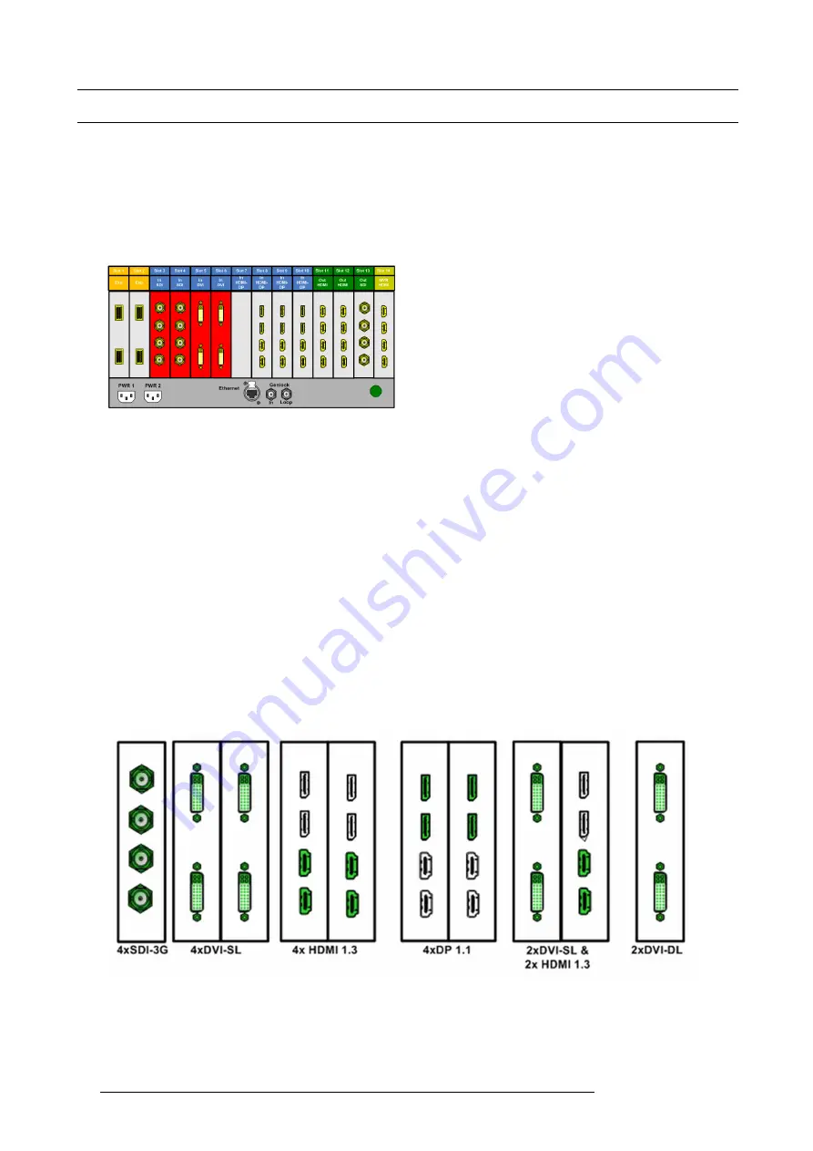
Input Card arrangement
Input cards occupy slots 3 through 10 and are right justi
fi
ed to slot 10. If there is an empty input slot between slots 3 and 10, all input
cards to the left of the empty slot are marked with red. Red indicates that although the cards will operate properly, inputs from these
cards will not be available at the multiviewer.
Image 6-14
Also, if the arrangement of the cards in the E2 unit doesn’t match the GUI arrangement, the corresponding card in the con
fi
guration
list and in the diagram area will be grayed out.
Finally, if the card in the slot is of different type, then again the slot in the diagram will be greyed out.
Input Connector Grouping
The connectors can also be grouped together to de
fi
ne a 3D or a 4K inputs. For example, 2 DVI connectors can be con
fi
gured for
a 3D Left and Right eye signals and 4 SDI connectors can be con
fi
gured as a 4K input.
There several rules that apply when de
fi
ning an input con
fi
guration:
1.
Every Input connector can only be assigned to one input (future software release will support assignment of one input connector
to multiple inputs).
2.
Input types in the same con
fi
guration must be of the same type and in the same slot or in adjacent slots. For example, cannot
have a HDMI connector and an SDI connector in the same input con
fi
guration. Exception to this is the HDMI and DVI connec-
tors.
3.
An input can be de
fi
ned from one, two or four connectors.
4.
Once an input connector is assigned to an input that already contains another one.
5.
Maximum of 4 connectors can be assigned to a layer.
6.
Maximum of 8 connectors can be assigned to a background.
7.
Maximum of 128 input con
fi
gurations can be assigned.
Examples of 4K Valid Inputs:
Image 6-15
Examples of valid 3D Inputs:
84
R5905948 E2 12/12/2014
Summary of Contents for Event Master E2
Page 1: ...E2 User s guide R5905948 00 12 12 2014...
Page 8: ...Table of contents 4 R5905948 E2 12 12 2014...
Page 16: ...2 Safety 12 R5905948 E2 12 12 2014...
Page 32: ...3 General 28 R5905948 E2 12 12 2014...
Page 82: ...6 GUI orientation Image 6 8 78 R5905948 E2 12 12 2014...
Page 94: ...6 GUI orientation Image 6 20 90 R5905948 E2 12 12 2014...
Page 115: ...6 GUI orientation Image 6 37 Thumbnail view Image 6 38 R5905948 E2 12 12 2014 111...
Page 186: ...7 System Setup 182 R5905948 E2 12 12 2014...
Page 192: ...8 Updating firmware 188 R5905948 E2 12 12 2014...
Page 196: ...9 General operation example Image 9 3 192 R5905948 E2 12 12 2014...
Page 213: ...9 General operation example Image 9 25 R5905948 E2 12 12 2014 209...
Page 216: ...9 General operation example 212 R5905948 E2 12 12 2014...
Page 220: ...10 Maintenance 10 2 Process Overview Flow chart Image 10 2 216 R5905948 E2 12 12 2014...
Page 281: ...10 Maintenance Disregard the heatsink from the spare kit R5905948 E2 12 12 2014 277...
Page 282: ...10 Maintenance 278 R5905948 E2 12 12 2014...
Page 288: ...11 Environmental information 284 R5905948 E2 12 12 2014...
Page 298: ...B Remote Control Protocol 294 R5905948 E2 12 12 2014...
Page 299: ...C Troubleshooting C TROUBLESHOOTING R5905948 E2 12 12 2014 295...
Page 300: ...C Troubleshooting 296 R5905948 E2 12 12 2014...


