6. Getting started
1 2 3 4 5
6 7 8 9 0
ME N U
EXI T
EN TE R
R GB
ST BY PA US ETEX T
PA TT ERN
W I N DOWPI P
L EN S
R I GGI N G
A UT O
2
1
3
P US H
2
1
3
P US H
P C Ca rd
Po rt 1
Po rt 2
10 /1 00 Ba sed -T
U SB
Di agno sti c c ode
IR rec ei ver
S td /ON
Wa rn in g I R
R em ot e
CT RL in
R em ot e
CT RL o ut
RS 23 2/ 42 2 ou t
RS 23 2/ 422 i n
HD SD I - SDI i np ut
In pu t 1
In pu t 2
Lo op o ut put
S yn c OK
Sel
S yn c OK
Sel
S yn c OK
Sel
DV I i np ut
5-cab le inp ut
R /P r G/ Y/ Vi deo B/ Pb
H/ S
V/ Cs
Image 6-5
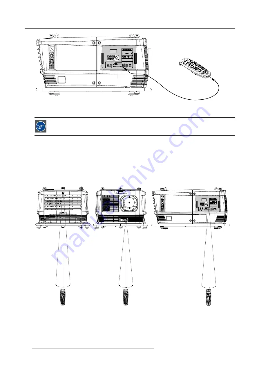
2. Plug the other end in the small connector in the input panel of the projector labeled
Remote CTRL in
.
The Remote connection uses a standard two wire cable terminated on each end with a 3.5 mm male
(mono/stereo) phone jack.
This cable is not delivered but is available in most electronic or audio shops.
Hardwired to the XLR input
1. Plug one end of the remote cable in the connector on the bottom of the RCU
2. Plug the other end in the big connector in the input panel of the projector labelled
Remote CTRL in
.
Directly to one of the IR sensors
When using the wireless remote control, make sure you are within the effective operating distance (30m, 100ft in a straight line). The
remote control unit will not function properly if strong light strikes the sensor window or if there are obstacles between the remote
control unit and the projector IR sensor.
1
2
3
4
5
6
7
8
9
0
ME N U
EXI T
EN TE R
R GB
ST BYPA US E
TEX T
PA TT ERN
W I N DOW
PI P L EN S
R I GGI N G
A UT O
2 1
3
P US H
2 1
3
P US H
P C Ca rd
Po rt 1
Po rt 2
10 /1 00 Ba se d-T
U SB
Di agn osti c c ode IR rec ei ve r
S td /ON
Wa rn in g
I R
R em ot e
CT RL in
R em ot e
CT RL o utRS 23 2/ 42 2 ou t
RS 23 2/ 422 i n
HD SD I - SDI i np ut
In pu t 1In pu t 2
Lo op o ut put
S yn c OK
Sel
S yn c OK
Sel
S yn c OK
Sel
DV I i np ut
5-cab le inp ut
R /P rG/ Y/ Vi deo
B/ Pb H/ S V/ Cs
F1 F2
F3 F4
F5
A
DJ
E X
I T
E N
T
E
R
P A
US
E
PHASE
T E
XT
SHARPN
T
I
NT
CO
L O
R
BR
I G
HT
N
CO
NT
R
T
R
EB
L E
BA
L A
NC
E
BA
SS
VO
L
9 0
7
8
5
6
3 4
1
2
F1
F2 F3 F4
F5
A
DJ
E X
I T
E N
T
E
R
P A
USE
PHASE
T E
XT
SHARPN
T
I
NT
CO
L O
R
BR
I GHT
N
CO
NT
R
T
R
EB
L E
BA
L A
NC
E
BA
SS
VO
L
9 0
7
8
5
6
3 4
1
2
F1
F2 F3 F4
F5
A
DJ
E X
I T
E N
T
E
R
P A
USE
PHASE
T E
XT
SHARPN
T
I
NT
CO
L O
R
BR
I GHT
N
CO
NT
R
T
R
EB
L E
BA
L A
NC
E
BA
SS
VO
L
9 0
7
8
5
6
3 4
1
2
45°
45°
45°
45°
45°
45°
Image 6-6
RCU to one of the IR sensors
48
R5976921 FLM R20+ PERFORMER 15/03/2010
Summary of Contents for FLM R20+ Performer
Page 1: ...FLM R20 Performer Users manual R9004430 R5976921 11 15 03 2010 ...
Page 34: ...3 Physical installation 30 R5976921 FLM R20 PERFORMER 15 03 2010 ...
Page 46: ...5 Connections 42 R5976921 FLM R20 PERFORMER 15 03 2010 ...
Page 62: ...7 Start up of the Adjustment Mode 58 R5976921 FLM R20 PERFORMER 15 03 2010 ...
Page 72: ...8 Input menu 68 R5976921 FLM R20 PERFORMER 15 03 2010 ...
Page 98: ...9 Image menu 94 R5976921 FLM R20 PERFORMER 15 03 2010 ...
Page 114: ...10 Layout menu Image 10 65 Image 10 66 Image 10 67 110 R5976921 FLM R20 PERFORMER 15 03 2010 ...
Page 120: ...11 Lamp menu 116 R5976921 FLM R20 PERFORMER 15 03 2010 ...
Page 148: ...12 Alignment menu 144 R5976921 FLM R20 PERFORMER 15 03 2010 ...
Page 168: ...13 Projector control 164 R5976921 FLM R20 PERFORMER 15 03 2010 ...
Page 184: ...14 Service menu 180 R5976921 FLM R20 PERFORMER 15 03 2010 ...
Page 204: ...17 Removal of the projector covers 200 R5976921 FLM R20 PERFORMER 15 03 2010 ...
Page 208: ...A Dimensions 204 R5976921 FLM R20 PERFORMER 15 03 2010 ...
Page 216: ...C DMX chart 212 R5976921 FLM R20 PERFORMER 15 03 2010 ...
Page 224: ...D Troubleshooting 220 R5976921 FLM R20 PERFORMER 15 03 2010 ...
Page 232: ...F Order info 228 R5976921 FLM R20 PERFORMER 15 03 2010 ...
Page 240: ...Index 236 R5976921 FLM R20 PERFORMER 15 03 2010 ...


