background image

5. Input and Communication

5.3

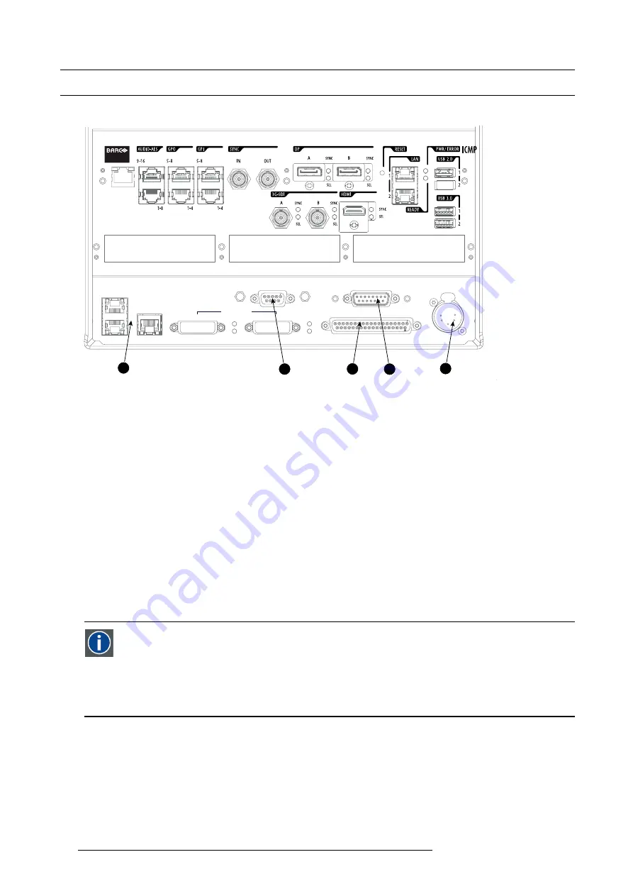
Communication ports of the HDQ projector

Location of the communication ports

1

3

5

2

4

GENERAL PURPOSE IN/OUT

DVI A

DVI B

DVI INPUT

SEL

SYNC OK

SEL

SYNC OK

10 / 100 / 1000 BASE-T

RS232 IN

3D INTERFACE

PERIPHERAL PORT

1

2

3

Image 5-3
Communication ports

1

10/100/1000 base-T

2

RS232 IN

3

General purpose input/output (GPIO)

4

3D interface

5

Peripheral port

10/100/1000 BASE-T

The HDQ projector can be connected to a LAN (local area network) using one of the Ethernet ports (1). Once connected to the
LAN, users can access the projector from any location, inside or outside (if allowed) their company network using the Communicator
software. This software locates the projector on the network if there is a DHCP server or the user can insert the correct IP-address to
access the projector. Once accessed, it is possible to check and manipulate all the projector settings. Remote diagnostics, control
and monitoring of the projector can then become a daily and very simple operation. The network connectivity allows detection of
potential errors and consequently improve service time.

As there is a need to daisy chain projectors when they are on an Ethernet network, an Ethernet switch is built in. the incoming
network is hereby available for the internal PC and for the next device in the chain. In this way a ’star’ network interconnection can
be avoided. The switch used is a stand alone 10/100/1000Mbit Ethernet switch. This assures no in

fl

uence on the network speed.

RS232 IN

This female DB-9 connector allows you to use a standard serial cable up to 10 meter to connect the touch panel interface with the
projector. Note that the RS232 protocol is used on this connection.

RS232

An Electronic Industries Association (EIA) serial digital interface standard specifying the characteristics of the commu-
nication path between two devices using either D-SUB 9 pins or D-SUB 25 pins connectors. This standard is used for
relatively short-range communications and does not specify balanced control lines. RS-232 is a serial control standard
with a set number of conductors, data rate, word length and type of connector to be used. The standard speci

fi

es com-

ponent connection standards with regard to computer interface. It is also called RS-232-C, which is the third version
of the RS-232 standard, and is functionally identical to the CCITT V.24 standard. Logical ’0’ is > + 3V, Logical ’1’ is < -
3V. The range between -3V and +3V is the transition zone.

GENERAL PURPOSE IN/OUT

This 37 pin connector can be used to send or receive trigger signals from other devices. These input/output pins can be programmed
by macros created on the Communicator touch panel. See user’s guide of the Touch panel, section Macro editor, for more informa-
tion about this functionality. Note that the General Purpose Inputs accept 24 volt maximum.

3D INTERFACE

Optional port.

58

R5905823 HDQ 4K35 30/11/2015

Summary of Contents for HDQ 4K35

Page 1: ...HDQ 4K35 User and Installation manual R5905823 04 30 11 2015 ...

Page 2: ...Barco NV President Kennedypark 35 8500 Kortrijk Belgium Phone 32 56 36 82 11 Fax 32 56 36 883 86 Support www barco com en support Visit us at the web www barco com Printed in Belgium ...

Page 3: ...n could contain technical inaccuracies or typographical errors Changes are periodically made to the information in this publication these changes are incorporated in new editions of this publication The latest edition of Barco manuals can be downloaded from the Barco web site www barco com or from the secured Barco web site https www barco com en signin Guarantee and Compensation Barco provides a ...

Page 4: ......

Page 5: ...nt plate 52 5 Input and Communication 55 5 1 Introduction 56 5 2 Local keypad of the HDQ projector 57 5 3 Communication ports of the HDQ projector 58 5 4 Source input ports of the Barco HDQ 4K35 projector 60 5 5 ICMP status LEDs 63 5 6 ICMP reset 64 6 Starting up 65 6 1 Switching ON the HDQ 67 6 2 Switching OFF the HDQ 68 7 Maintenance 69 7 1 Cleaning the front dust filter 70 7 2 Cleaning the bott...

Page 6: ...chnical Regulations 98 B Environmental information 99 B 1 Disposal information 100 B 2 RoHS compliance 101 B 3 Production address 102 B 4 Importers contact information 103 Glossary 105 Index 107 2 R5905823 HDQ 4K35 30 11 2015 ...

Page 7: ...udes several cautions to prevent damage to the HDQ 4K35 Ensure that you understand and follow all safety guidelines safety instructions and warnings mentioned in this chapter before installing your HDQ 4K35 After this chapter additional warnings and cautions are given depending on the installation procedure Read and follow these warnings and cau tions as well R5905823 HDQ 4K35 30 11 2015 3 ...

Page 8: ...ritical components materials and insulation in order to protect the user or operator against risk of electric shock and energy hazard and having access to live parts Safety standards also impose limits to the internal and external temperature rises radiation levels mechanical stability and strength enclosure construction and protection against the risk of fire Simulated single fault condition test...

Page 9: ...o the projector mains terminals and unplug the power cord at UPS INLET for removal of all power from the projector Warning High leakage current Earth connection essential before connecting supply Do not allow anything to rest on the power cord Do not locate this projector where persons will walk on the cord Do not operate the projector with a damaged cord or if the projector has been dropped or da...

Page 10: ...afety cables for visible damage before operating the projector If the safety cables are damaged they must be replaced with new ones It is hazardous to operate without lens or shield Lenses shields or ultra violet screens shall be changed if they have become visibly damaged to such an extent that their effectiveness is impaired For example by cracks or deep scratches Warning Protection from ultravi...

Page 11: ...ead to the projector shutting down during operation The projector must always be installed in a manner which ensures free flow of air into its air inlets and unimpeded evacuation of the hot air from its cooling system In order to ensure that correct airflow is maintained and that the projector complies with Electromagnetic Compatibility EMC and safety requirements it should always be operated with...

Page 12: ...Unauthorized substitu tions may result in degraded performance and reliability fire electric shock or other hazards Unauthorized substitutions may void warranty Safety check Upon completion of any service or repairs to this projector ask the service technician to perform safety checks to determine that the product is in proper operating condition Possible explosion hazard Always keep in mind the c...

Page 13: ... are critical to the optimum use of the projection system Barco provides a guarantee relating to perfect manufacturing as part of the legally stipulated terms of guar antee Observing the specification mentioned in this chapter is critical for projector performance Neglecting this can result in loss of warranty WARNING Never transport the HDQ projector in an upside down position Failure to do so ca...

Page 14: ...air contam inants will culminate in extensive and irreversible ingrained optical damage At this stage cleaning of the internal optical units will be noneffective and impracticable Damage of this nature is under no circumstances covered under the manufacturer s warranty and may deem the warranty null and void In such a case the client shall be held solely responsible for all costs incurred during a...

Page 15: ...e the projector has arrived at its destination it needs to be removed from the cardboard box and the pallet in a safe manner and without damaging the projector How to unpack the projector 1 Loosen the banding by pulling the free end of the banding loop in the clip Remove the box cover Image 2 2 2 Unfold the top side of the outer cardboard box Take out the small box located between inner and outer ...

Page 16: ...jector with the supporting wooden board from the pallet A hoisting tool is recommended Make sure the 4 screws on the underside of the wooden board are accessible Release the projector from the supporting wooden board by removing the 4 screws Warning It is forbidden to lift up the projector with manpower use a hoisting tool instead Do not underestimate the weight of the projector The projector weig...

Page 17: ...epack your projector as it was originally packed at the factory A rubber foam inside a plastic bag is placed into the lens opening of the projector It s recommended to reuse this foam and plastic back each time you transport the projector This to prevent intrusion of dust and foreign particles The lens is delivered in a separate box R5905823 HDQ 4K35 30 11 2015 13 ...

Page 18: ...age was possibly roughly handled by the transport company In this case the instructions mentioned on the label should be followed which are adding a note on the bill of lading and informing the transport company and the Barco sales and service office as soon as possible Box content After unpacking the projector it is recommended to check if all following items where included Safety manual Quick st...

Page 19: ...sult in disrupting the air flow inside the projector caus ing overheating Overheating may lead to the projector shutting down during operation See Cleaning the front dust filter page 70 and Cleaning the bottom dust filters page 71 WARNING The projector is fan cooled and must be installed with sufficient space around the air inlets mini mum 20 cm 8 to ensure sufficient air flow Loose papers or othe...

Page 20: ...e input See Source input ports of the Barco HDQ 4K35 projector page 60 10 Select the input to which the source is connected Use Communicator to make the selection 11 Alignment of the projected image on the screen The projector can now be switched on to project its first image test pattern on the screen Then the image can be aligned with the screen size of the application Follow the next steps to a...

Page 21: ... Power input setup of the HDQ 4K35 Connecting the projector with the power net Connecting a UPS to the projector electronics Landscape and portrait mode Stacking multiple projectors Adjusting the multifunctional frame Aligning the projected image on the screen Aligning stacked projectors R5905823 HDQ 4K35 30 11 2015 17 ...

Page 22: ...r ence may occur while inserting the Lamp House 1 Image 3 1 Positioning the quarter turn screws 3 Grip the Lamp House by both handles 2 and 3 and place the front of the Lamp House on the base plate inside the lamp com partment of the projector lining up the foot of the Lamp House with the slots on the base Warning Be aware of the weight of the Lamp House Take the necessary precautions to avoid per...

Page 23: ...er connection of the projector 1 Remove the back cover of the projector See Removal of the back cover page 88 2 Release the 2 captive screws 1 3 Remove the power connection cover 2 3 4 2 1 Image 3 3 Power connection access The terminal barrier strip 3 and Y Δ configuration block 4 is accessible R5905823 HDQ 4K35 30 11 2015 19 ...

Page 24: ... Υ Δ connection A Υ connection B Δ connection Necessary tools Flat screw driver Wrench 10 mm Torque wrench 10 mm How to switch from a Υ connection to Δ connection 1 Loosen the 6 top nuts on the Υ Δ configuration block 1 to 6 Y Δ 1 2 3 4 5 6 B A C Image 3 5 Υ to Δ connection 2 Take off the mounted lins A B and C Two links above each other or mounted between the upper and middle pin A B and one link...

Page 25: ... Image 3 6 Δ to Υ connection 2 Take off the mounted links A B and C 3 Connect the right pins together Place 2 links between the upper pin and the middle pin A B and 1 link between the middle pin and the lower pin C R5905823 HDQ 4K35 30 11 2015 21 ...

Page 26: ...rcuit breaker maximum 40A How to connect the projector with the power net 1 Remove the back cover of the projector See Removal of the back cover page 88 2 Remove the power connection cover See Access to the power connection page 19 3 Loosen the cable gland fixation ring 1 Note The cable gland is specified for cables with a diameter between 11 mm and 21 mm 4 Push the stripped power supply cable 2 t...

Page 27: ...S according to the instructions of the manufacturer and the local regulations 2 Remove the short power link cable if present a Remove both fixation springs 1 by squeezing them together and pulling them away from the power plugs b Unplug both power plugs from the short power link cable 2 1 1 2 Image 3 8 3 Connect the power output cord from the UPS unit 1 to the UPS inlet socket of the projector rig...

Page 28: ...stall the second fixation spring on the power outlet socket to prevent losing it 1 1 Image 3 10 CAUTION The electrical connection with the UPS INLET socket of the projector must be done with a certified AC power supply cord minimum 0 75 mm or 18 AWG and minimum 300V CAUTION Do not use the power OUTLET socket of the projector to provide power to other equipment 24 R5905823 HDQ 4K35 30 11 2015 ...

Page 29: ...scape mode and is rotated in the frame for 3 An additional frame rotation of 12 of is allowed Landscape and portrait mode The projector can be used in landscape or portrait mode The illustrations below shows which positions are allowed and which are not A B C D E F Image 3 11 A Landscape mode allowed B Portrait mode allowed C Upside down disallowed D Turned over portrait mode disallowed E Upwards ...

Page 30: ...ersible damage to the projector WARNING It is not allowed to stack multiple projectors in portrait mode CAUTION When the projector is used in portrait mode always ensure the cooling liquid level is sufficient To check the cooling liquid level see Checking cooling liquid level page 74 26 R5905823 HDQ 4K35 30 11 2015 ...

Page 31: ...oisting tool instead Do not under estimate the weight of the projector The projector weights 210 kg 462 lb WARNING When the projector is suspended from a truss minimum four 4 clamps must be used to secure the projector The clamps must be fixed to the projector frame Use a truss which is capable of handling five 5 times the complete load of the system WARNING When the projector is suspended from a ...

Page 32: ...first projector 2 Make sure the pins of the lower frame fit in the holes of the upper frame Warning It is forbidden to lift up the projector with manpower use a hoisting tool instead Do not underestimate the weight of the projector The projector weights 210 kg 462 lb 4 Slide in the 4 pipe lynch pins 3 and secure them by swinging the lever 4 2 1 1 1 1 3 4 Image 3 14 Stacking projectors 5 Mount 2 tw...

Page 33: ...e upper frame and clasp the safety hook around the cable as illustrated Make sure that the falling distance is maximum 20 cm 8 If necessary before clasping the safety hook around the cable turn the cable a few time around the frame c Repeat this procedure for the other safety cable on the other side of the frame 2x 2x Image 3 15 R5905823 HDQ 4K35 30 11 2015 29 ...

Page 34: ...5 mm Allen wrench 17 mm wrench How to inclinate and rotate the projector in the frame 1 Release the locking screw s 1 on the adjustment mechanism s on the back of the frame Use a 2 5 mm Allen wrench 2 Turn the left and right adjustment screw 2 anti clockwise to lower the back of the projector Or clockwise to rise the back of the projector Note A 17 mm wrench can be used to turn the adjustment scre...

Page 35: ...mm Allen wrench Tip Only the most reachable locking screw s on the adjustment rod may have been secured previously 2 Turn the adjustment rod 2 clockwise to skew the projector clockwise Or anti clockwise to skew the projector anti clockwise 3 Tighten the locking screw s 1 Use a 2 5 mm Allen wrench Tip Only secure the most reachable locking screw s 1 2 Image 3 18 Skewing the projector R5905823 HDQ 4...

Page 36: ...creen Rotation Image 3 19 3 Adjust the inclination of the projector Adjust until the outline of the hatch pattern is most symmetric with the projection screen Inclination Image 3 20 4 Adjust the skew of the projector Adjust until the outline of the hatch pattern is most symmetric with the projection screen Skew Image 3 21 5 Shift the hatch pattern horizontally and vertically until the outline of t...

Page 37: ...he Lens zoom buttons to zoom the image Or use the zoom buttons on the local keypad Zoom Image 3 23 7 Repeat from step 2 until the hatch pattern of the stacked projector is perfectly aligned with the projection screen 8 Focus the projector to the screen until the hatch pattern is perfectly sharp Use Communicator software to focus In the navigation pane click on Configuration Lens The Lens settings ...

Page 38: ...sharp and must have a perfect rectangle outline If this is not the case readjust the reference projector before aligning the other stacked projector s with the reference hatch pattern 3 Project the same internal hatch pattern with the stacked projector In the navigation pane click on Control Test Patterns and select a hatch pattern 4 Adjust the rotation of the stacked projector with respect to the...

Page 39: ...ings menu opens Use the Lens shift buttons to shift the image Or use the shift buttons on the local keypad Shift Image 3 27 8 Zoom the hatch pattern in or out until the outline of the hatch pattern matches exactly the outline of the reference hatch pattern Use Communicator software to zoom In the navigation pane click on Configuration Lens The Lens settings menu opens Use the Lens zoom buttons to ...

Page 40: ...he hatch pattern is perfectly sharp Use Communicator software to focus In the navigation pane click on Configuration Lens The Lens settings menu opens Use the Lens focus buttons to focus the image In case of a triple stacked standing projector configuration table mount adjust and align the reference pro jector first than the middle projector and finally the uppermost projector 36 R5905823 HDQ 4K35...

Page 41: ...ribed how you can perform the Scheimpflug adjustment CAUTION Never transport the projector with a lens mounted in the Lens Holder Always remove the lens before transporting the projector Neglecting this can damage the Lens Holder and Prism Overview Available lenses Lens selection Lens installation Lens removal Installing the lens fixation mechanism Removing the lens fixation mechanism Lens shift z...

Page 42: ...Product Number Zoom range Image R9852950 1 0 fixed image 4 1 R9852090 1 45 1 8 image 4 2 R9852092 1 8 2 4 image 4 3 R9852094 2 2 3 image 4 4 R9852100 2 8 5 5 image 4 5 R9852920 5 5 8 5 image 4 6 R9856294 1 35 1 86 image 4 7 R9856297 1 46 2 10 image 4 8 R9856300 1 65 2 60 image 4 9 Image 4 1 R9852950 Image 4 2 R9852090 Image 4 3 R9852092 Image 4 4 R9852094 Image 4 5 R9852100 Image 4 6 R9852920 38 R...

Page 43: ...4 Lenses Lens Holder Image 4 7 R9856294 Image 4 8 R9856297 Image 4 9 R9856300 R5905823 HDQ 4K35 30 11 2015 39 ...

Page 44: ... www barco com en tools lenscalculator to determine the possible lenses for your configuration The Lens Calculator window opens Image 4 10 Lens calculator The Lens Calculator can also be used to determine the position of the projector when the lens type and screen width is known Due to lens tolerances the results of calculated values may be different from measured values These differ ence may vary...

Page 45: ...ns 1 Remove the plastic lens holder cover a Put the lock 1 into the unlock position b Take out the plastic cover 1 2 1 2 Image 4 11 2 Take the lens assembly out of its packing material and remove the lens caps on both sides 3 Place the lens holder in the unlocked position by moving the lens lock handle 1 towards the lens power supply socket 2 1 2 3 Image 4 12 Unlock lens holder R5905823 HDQ 4K35 3...

Page 46: ... the socket 2 Warning Do not release the Lens yet as the Lens may fall out of the Lens Holder 7 Secure the lens in the lens holder by sliding the lens lock handle into the locked position which is away from the lens power supply socket Ensure the lens touches the front plate of the lens holder Image 4 14 Fix lens 8 Continue with the installation of the lens fixation mechanism see Installing the le...

Page 47: ...holder Image 4 16 Remove lens It s recommended to place the Lens caps of the original Lens packaging back on both sides of the removed Lens to protect the optics of the Lens It s recommended to place the foam rubber of the original projector packaging back into the Lens opening to prevent intrusion of dust Note that this foam rubber is packed in a plastic bag to prevent the dust emitted by the foa...

Page 48: ...ated below The fixation brackets must prevent the lens from coming loose from the Lens Holder 2 Secure the fixation brackets by installing a nut 2 on each bracket Use a 10 mm wrench 1 1 2 1 1 Image 4 17 Installing the lens fixation mechanism Depending on which lens is used it may not always be possible to install the fixation brackets at the positions showed on the illustration In that case the br...

Page 49: ...ary tools 10 mm wrench How to remove the lens fixation mechanism 1 Remove the nuts 2 from the fixation brackets Use a 10 mm wrench 2 Remove the fixation brackets 1 from the Lens Holder 2 1 1 Image 4 18 Removing the lens fixation mechanism R5905823 HDQ 4K35 30 11 2015 45 ...

Page 50: ...he navigation pane on Configuration Lens How to zoom in or out 1 Is the zoom lens equipped with a motorized zoom If yes use the and zoom keys on the local keypad to zoom in or out Image 4 20 If no use the zoom barrel on the lens to zoom in or out How to focus 1 Use the and focus keys on the local keypad to focus the image on the screen Image 4 21 Take into account that the lens focus may slightly ...

Page 51: ...e available range in the other direction Necessary tools 3 mm Allen wrench How to shift the Lens Holder 1 Remove the front projector cover See Removal of the front cover page 86 2 Loosen the 4 screws 1 until the central part of the Lens Holder becomes loose Use a 3 mm Allen wrench 3 Shift the central part up or down as desired The lowermost middle and uppermost shift positions are marked on the Le...

Page 52: ...ne Lp3 Lp4 SCREEN DMD Lp1 Lp2 Fp1 Fp2 SCREEN DMD Lp3 Lp4 Fp3 Fp4 Scheimpflug Image 4 23 Scheimpflug principle Scheimpflug principle The plane of sharp focus can be changed so that any plane can be brought into sharp focus When the DMD plane and lens plane are parallel the plane of sharp focus will also be parallel to these two planes If however the lens plane is tilted with respect to the DMD plan...

Page 53: ...4 set screws A B C and D by 1 cm See image 4 24 4 Fully loosen lock nut 4 See image 4 24 5 Optimize the focus of the projected image as follows a Turn the Scheimpflug adjustment nuts 1 2 and 3 until the front of the nut is equally aligned with the front of the threaded rod b Adjust the focus in the center of the screen F using the motorized focus control 1 2 3 F Image 4 26 Center focusing 6 Sharpe...

Page 54: ...F Image 4 27 Left bottom focusing 7 Sharpen bottom right corner of the screen by adjusting nut 2 2 F Image 4 28 Right bottom focusing 8 Sharpen top right corner of the screen by adjusting nut 3 50 R5905823 HDQ 4K35 30 11 2015 ...

Page 55: ...focusing 9 Repeat from step 6 until the projected focus pattern is as sharp as possible in the center left right top and bottom of the screen 10 Continue with the Fixation of the lens holder front plate procedure R5905823 HDQ 4K35 30 11 2015 51 ...

Page 56: ...rew at the lower left of the Lens Holder Note Ensure that the edges of the projected test pattern remain in place on the screen Any movement of the image will affect the Scheimpflug adjustment 4 Fasten the lock nut reference 21 image 4 31 of the three set screws Use a 10mm nut driver Ensure the image doesn t move 11 21 11 Image 4 31 5 Gently turn by hand the Scheimpflug adjustment nut at the lower...

Page 57: ...4 Lenses Lens Holder 4 14 24 Image 4 32 7 Fasten the lock nut at the lower left of the Lens Holder Use a 10mm nut driver R5905823 HDQ 4K35 30 11 2015 53 ...

Page 58: ...4 Lenses Lens Holder 54 R5905823 HDQ 4K35 30 11 2015 ...

Page 59: ...NPUT AND COMMUNICATION Overview Introduction Local keypad of the HDQ projector Communication ports of the HDQ projector Source input ports of the Barco HDQ 4K35 projector ICMP status LEDs ICMP reset R5905823 HDQ 4K35 30 11 2015 55 ...

Page 60: ...le and an input controller module 1 2 3 4 5 6 A B C G D E F Image 5 1 A Local keypad button module B Communication ports C Socket for security key D Fan controller module E Display ports F HDMI port G 3G SDI ports CAUTION A unit may only be removed by qualified service personnel Removing a unit will result in an authorization request upon starting 56 R5905823 HDQ 4K35 30 11 2015 ...

Page 61: ...key has a marker area 1 where you can write down the name of the macro Standby key Standby key 3 switches ON or OFF the lamp and lamp electronics The lamp cooling fans remain active for about 5 minutes The speed of the other fans is reduced The backlight color of the standby key remains red in standby mode and changes to green in operation mode Dowser key The dowser key 4 opens or closes the dowse...

Page 62: ...rk interconnection can be avoided The switch used is a stand alone 10 100 1000Mbit Ethernet switch This assures no influence on the network speed RS232 IN This female DB 9 connector allows you to use a standard serial cable up to 10 meter to connect the touch panel interface with the projector Note that the RS232 protocol is used on this connection RS232 An Electronic Industries Association EIA se...

Page 63: ... Communication Can be used to connect external 3D devices to the projector All signals necessary for 3D projection can be provided via this con nector PERIPHERAL PORT For future use R5905823 HDQ 4K35 30 11 2015 59 ...

Page 64: ...monitor though it can also be used to transmit audio USB and other forms of data VESA designed it to replace VGA DVI and FPD Link Backward compatibility to VGA and DVI by using active adapter dongles enables users to use DisplayPort fitted video sources without replacing existing display devices SMPTE Society of Motion Picture and Television Engineers A global organization based in the United Stat...

Page 65: ... doubles the SDI data rates to 2 97 Gbps using the same 75 ohm coaxial cable This new standard also called 3 Gbps 3G SDI enables higher resolution of picture quality required for 1080p and digital cinema DP Input formats DP1 1a 4 lanes RBR HBR Audio none Content Protection HDCP 1 4 Colordepth 8 bit color and 10 bit color 3D stereo mode frame sequential embedded stereosync on DP required from the s...

Page 66: ...2160p at 25Hz 3840 x 2160p at 24Hz 1920 x 1080p at 60Hz 1280 x 720p at 60Hz 640 x 480p at 60Hz 800 x 600p at 60Hz 1024 x 768p at 60Hz 1400 x 1050p at 60Hz 1280 x 1024p at 60Hz 1024 x 768p at 60Hz 1280 x 960p at 60Hz 1920 x 1080p at 50Hz 1920 x 1080p at 24Hz 1920 x 1080p at 25Hz 1920 x 1080p at 30Hz 1280 x 720p at 50Hz 720 x 480p at 60Hz VIC 2 720 x 480p at 60Hz VIC 3 720 x 576p at 50Hz Notes Inclu...

Page 67: ... Red Off Board reset Blinking Green Off Boot loader Blinking Green Blinking Orange Operating System start up Blinking Green Orange Security Manager Image Integrity tests Blinking Green Blinking Yellow Security Manager Self Test Blinking Green Yellow Security Manager FPGA self test Green Blinking Orange Update ongoing Green Blinking Green FIPS ok Application startup Green Green Power on No Error Bl...

Page 68: ...re requested to end After a few seconds the ICMP is requested to restart The READY LED on the front panel of the ICMP starts to blink orange In case the ICMP is installed in DP4K L series projector the lasers are switched off and the projector remains in the same mode e g Conditioned The Star button on the local keypad starts blinking green After the reset of the ICMP the lasers are switched on ag...

Page 69: ...6 Starting up 6 STARTING UP R5905823 HDQ 4K35 30 11 2015 65 ...

Page 70: ...6 Starting up 66 R5905823 HDQ 4K35 30 11 2015 ...

Page 71: ...municator via PC 7 Press the power switch to switch ON the projector As a result the projector starts up in standby So the lamp is OFF and the dowser closed No internal pattern is selected The communicator touch panel starts its initialization procedure When 0 is visible the projector is switched OFF When 1 is visible the projector is switched ON 8 Press the STANDBY button on the local keypad or u...

Page 72: ...municator Touch Panel to switch the projector from operation to standby As a result the lamp turns off but the fans remain turning to cool down the projector 2 Let the projector cool down at least 5 minutes or until the speed of the fans decreases 3 Switch OFF the projector with the power switch 68 R5905823 HDQ 4K35 30 11 2015 ...

Page 73: ...t filters Cleaning the lens Cleaning the exterior of the projector Checking cooling liquid level Topping up the cooling liquid reservoir Removal of the Lamp House Realignment of the lamp in its reflector Authorization to clear security warning on the projector R5905823 HDQ 4K35 30 11 2015 69 ...

Page 74: ...filter 1 Remove the input cover See Removal of the input cover page 84 2 Slide out the front dust filter 1 from the projector 3 Remove most contamination from the filters with a vacuum cleaner in another room or outside 4 Blow the remaining dust away with compressed air in another room or outside 5 Position the filter with the up sign 2 upwards and slide it in until it clicks into position 1 2 Ima...

Page 75: ...rs 1 Remove the left cover See Removal of the left cover page 90 2 Slide out the bottom dust filters 1 and 2 from the projector 3 Remove most contamination from the filter with a vacuum cleaner in another room or outside 4 Blow the remaining dust away with compressed air in another room or outside 5 Position the filters with the flanges upwards 3 and slide them in until they click into position 1 ...

Page 76: ... together with a clean lens cleaning cloth to remove the dust and contamination Use big wipes in one single direction Warning Do not wipe back and forwards across the lens surface as this tends to grind dirt into the coating 3 Use a dry lens cleaning cloth to remove left liquid or stripes Polish with small circles 4 If there are still fingerprints on the surface wipe them off with lens cleaner tog...

Page 77: ...NLET for removal of all power from the projector How to clean the exterior of the projector 1 Disconnect the power to the projector mains terminals and unplug the power cord at UPS INLET for removal of all power from the projector 2 Clean the housing of the projector with a damp cloth Stubborn stains may be removed with a cloth lightly dampened with a mild detergent solution R5905823 HDQ 4K35 30 1...

Page 78: ...s immediate attention How to check the cooling liquid level 1 Remove the left projector cover See Removal of the left cover page 90 2 Check the cooling liquid level in the reservoir Image 7 3 Checking the cooling liquid level If the current cooling liquid level is somewhere between Min and Max no action is required If the current cooling liquid level is approaching the Min level point check for le...

Page 79: ...mes CAUTION Tighten the filler cap sufficiently to avoid cooling liquid leakage Tighten to a torque of 7 Nm Handling the cooling liquid Avoid contact of the liquid with Eyes Skin and Clothing Avoid inhaling noxious fumes Conserve the product in the original package and in a well ventilated room Personal protection rules Handle the cooling liquid in a well ventilated room Under no circumstances eat...

Page 80: ...Tighten the filler cap sufficiently to avoid cooling liquid leakage Tighten to a torque of 7 Nm 5 Install the left projector cover See Removal of the left cover page 90 CAUTION Never fill the cooling liquid reservoir above the Max level mark 76 R5905823 HDQ 4K35 30 11 2015 ...

Page 81: ... projector 1 Remove the lamp cover 2 Release the two retaining screws 1 at the base of the Lamp House Use a 10 mm nut driver or a flat screwdriver 3 Remove the Lamp House a Grip the Lamp House with the bottom handle 2 and partially slide it out of the Lamp House compartment b Grip the Lamp House with the top handle also 3 and remove it completely from the projector c Place the Lamp House on a soli...

Page 82: ...Remove the lamp cover See Removal of the lamp cover page 82 2 Start up the projector enter the menu structure and select Lamp Z axis 3 Loosen the Z axis lock screw 2 4 Carefully turn the thumb screw 1 at the rear of the Lamp House clockwise for maximum light output Once over the maximum turn slightly counterclockwise to reach the maximum light output again 1 2 Image 7 6 Z axis alignment 5 Secure t...

Page 83: ...rity key in the security socket D 1 1 2 3 4 5 6 Image 7 7 Keypad The color of the backlight of the numeric keys 1 to 6 of the local keypad changes from blue to yellow 4 Enter pin code within 5 seconds In case no keys are pressed the color of the backlight of the numeric keys 1 to 6 changes back to blue In case of an incorrect code entry the color of the backlight of the numeric keys changes to red...

Page 84: ...7 Maintenance 80 R5905823 HDQ 4K35 30 11 2015 ...

Page 85: ...Removal of the lamp cover Installation of the lamp cover Removal of the input cover Installation of the input cover Removal of the front cover Installation of the front cover Removal of the back cover Installation of the back cover Removal of the left cover Installation of the left cover Location of the covers The image below shows the location of the projector covers Each cover can be removed ind...

Page 86: ... Flat screwdriver How to remove the lamp cover 1 Release the 2 captive screws 1 2 Release the 2 locks by sliding them towards each other 2 Pull the bottom side away from the projector 3 Remove the cover 3 2 2 1 1 1 1 1 1 2 2 2 2 3 3 Image 8 2 Removing the lamp cover 82 R5905823 HDQ 4K35 30 11 2015 ...

Page 87: ... to install the lamp cover 1 Position the lamp cover on its place and slide it towards the projector 1 2 Slide the locks to each other 2 and push the cover against the projector Release the locks 3 Tighten the 2 captive screws 3 2 2 3 3 3 3 3 3 2 2 2 2 1 1 Image 8 3 Installing the lamp cover R5905823 HDQ 4K35 30 11 2015 83 ...

Page 88: ...cover Necessary tools Flat screwdriver How to remove the input cover 1 Release the 2 captive screws 1 2 Pull back the cover until the locking mechanism at the bottom releases 3 Remove the cover 2 1 1 1 1 1 1 2 2 Image 8 4 Removing the input cover 84 R5905823 HDQ 4K35 30 11 2015 ...

Page 89: ...crewdriver How to install the input cover 1 Position the input cover on its place and slide it towards the projector 1 2 Push the cover against the projector until the locks at the bottom snap 3 Tighten the 2 captive screws 2 2 2 2 2 2 2 1 1 Image 8 5 Installing the input cover R5905823 HDQ 4K35 30 11 2015 85 ...

Page 90: ...cedure assumes that the lens is already removed from the projector How to remove the front cover 1 Remove the rubber dust ring from the Lens Holder Image 8 6 Removing the rubber dust ring 2 Release the captive screw 1 3 Pull back the cover until the locking mechanism at the top releases 4 Remove the cover 2 1 1 1 1 2 2 Image 8 7 Removing the front cover 86 R5905823 HDQ 4K35 30 11 2015 ...

Page 91: ...Position the front cover on its place and slide it towards the projector 1 2 Push the cover against the projector until the locks at the top snap 3 Tighten the captive screw 2 2 2 2 2 1 1 Image 8 8 Installing the front cover 4 Reinstall the rubber dust ring around the Lens Holder Image 8 9 Installing the rubber dust ring R5905823 HDQ 4K35 30 11 2015 87 ...

Page 92: ... cover Necessary tools Flat screwdriver How to remove the back cover 1 Release the 2 captive screws 1 2 Pull back the cover until the locking mechanism at the top releases 3 Remove the cover 2 1 1 1 1 1 1 2 2 Image 8 10 Removing the back cover 88 R5905823 HDQ 4K35 30 11 2015 ...

Page 93: ... screwdriver How to install the back cover 1 Position the back cover on its place and slide it towards the projector 1 2 Push the cover against the projector until the locks at the top snap 3 Tighten the 2 captive screws 2 2 2 2 2 2 2 1 1 Image 8 11 Installing the back cover R5905823 HDQ 4K35 30 11 2015 89 ...

Page 94: ...aptive screws 1 2 Release the 2 locks by sliding them towards each other 2 Pull the bottom side away from the projector 3 Lift the cover up a little 3 and slide it out on the front side of the frame 5 while turning the back of the cover away from the projector 4 2 2 1 1 3 5 4 4 2 2 2 2 1 1 1 1 Image 8 12 Removing the left cover 90 R5905823 HDQ 4K35 30 11 2015 ...

Page 95: ... front side of the frame 1 while turning the back of the cover towards the projector 2 Lower the cover until it rests on the top side of the projector 3 2 Slide the locks to each other 4 and push the cover against the projector Release the locks 3 Tighten the 2 captive screws 5 4 4 5 5 3 1 4 2 5 5 5 5 4 4 4 4 Image 8 13 Installing the left cover R5905823 HDQ 4K35 30 11 2015 91 ...

Page 96: ...8 Removal and installation of the projector covers 92 R5905823 HDQ 4K35 30 11 2015 ...

Page 97: ...A Dimensions and specifications A DIMENSIONS AND SPECIFICATIONS R5905823 HDQ 4K35 30 11 2015 93 ...

Page 98: ...A Dimensions and specifications 94 R5905823 HDQ 4K35 30 11 2015 ...

Page 99: ...nsions of the Barco HDQ 4K35 Dimensions 700 470 1248 755 1024 1321 940 75 589 351 502 368 895 870 897 631 410 691 Image A 1 Dimensions of the Barco HDQ 4K35 Lens to lens distance with stacked projectors 870 mm R5905823 HDQ 4K35 30 11 2015 95 ...

Page 100: ...y 2 160 HDMI ready 3GHDSDI ready Sealed DLP core Standard Optical dowser Standard Orientation table side portrait WARP external optional MCM warp Integrated web server yes projector control board Optional Inputs NA Input resolutions Up to 4K 60p Software tools DC Communicator Network connection 10 100 base T RJ 45 connection Power requirements 200 240V 380 400V 50 60Hz Max power consumption 8 000W...

Page 101: ...A Dimensions and specifications Warranty 3 years standard extendable up to 5 years 10 R5905823 HDQ 4K35 30 11 2015 97 ...

Page 102: ...A Dimensions and specifications A 3 Technical Regulations Certificates Image A 2 EAC mark 10 Image A 3 Rohs RoHS Image A 4 Rohs OK Image A 5 CE mark 98 R5905823 HDQ 4K35 30 11 2015 ...

Page 103: ...B Environmental information B ENVIRONMENTAL INFORMATION Overview Disposal information RoHS compliance Production address Importers contact information R5905823 HDQ 4K35 30 11 2015 99 ...

Page 104: ...eries covered by the Directive 2006 66 EC which must be collected and disposed of separately from municipal waste If the battery contains more than the specified values of lead Pb mercury Hg or cadmium Cd these chemical symbols will appear below the crossed out wheeled bin symbol By participating in separate collection of batteries you will help to ensure proper disposal and to prevent potential n...

Page 105: ...o o 本表格依据SJ T 11364的规定编制 This table is prepared in accordance with the provisions of SJ T 11364 O 表示该有毒有害物质在该部件所有均质材料中的含量均在 GB T 26572 标准规定的限量要求以下 O Indicates that this toxic or hazardous substance contained in all of the homogeneous materials for this part is below the limit requirement in GB T 26572 X 表示该有毒有害物质至少在该部件的某一均质材料中的含量超出 GB T 26572 标准规定的限量要求 X Indicates that this toxic or hazardous subs...

Page 106: ...视 北京 电子有限公司 No 16 Changsheng Road Changping District 102200 Beijing P R C 北京市昌平区中关村科技园区昌平园昌盛路16号 邮政编码 102200 Made in information The made in country is indicated on the product ID label on the product itself Production date The month and year of production is indicated on the product ID label on the product itself 102 R5905823 HDQ 4K35 30 11 2015 ...

Page 107: ... B 4 Importers contact information Contact To find your local importer contact Barco directly or one of Barco s regional offices via the contact information given on Barco s web site www barco com R5905823 HDQ 4K35 30 11 2015 103 ...

Page 108: ...B Environmental information 104 R5905823 HDQ 4K35 30 11 2015 ...

Page 109: ...imedia Interface is a compact audio video interface for transferring uncompressed video data and com pressed uncompressed digital audio data from a HDMI compliant device the source device to a compatible computer monitor video projector digital television or digital audio device HDMI is a digital replacement for existing analog video standards Reference projector In case of a standing configuratio...

Page 110: ...Glossary 106 R5905823 HDQ 4K35 30 11 2015 ...

Page 111: ...3 Removal 82 Left cover 90 91 Installation 91 Removal 90 Removal 81 D Dimensions 93 95 Projector 95 E Environmental information 99 101 Disposal information 100 RoHS compliance 101 F Fixate 52 Lens Holder front plate 52 Focus 46 front dust filter 70 dust filter 70 front 70 G General 9 General considerations 4 I ICMP reset 64 Important safety instructions 5 Importer 103 Initial inspection 14 Input 5...

Page 112: ...ton 64 S Safety 3 5 8 Battery explosion 8 Cooling liquid circuit 6 Electrical shock 5 Fire hazard 7 Personal injury 6 Projector damage 7 Servicing 8 Scheimpflug 48 Shift 46 Specifications 93 96 Barco HDQ 4K35 96 Stack 27 Stacking 27 Starting up 65 67 Switching on 65 67 Status LEDs 63 Switching OFF 68 Switching on 65 67 T Technical Regulations 98 U Unpacking the projector 11 User definition 4 W War...

Reviews: