


R5975059A BARCOVISION 708 200498
RANDOM ACCESS ADJUSTMENT MODE
RANDOM
ACCESS
ADJUSTMENT
MODE
R5975059A BARCOVISION 708 200498
RANDOM ACCESS ADJUSTMENT MODE
RANDOM
ACCESS
ADJUSTMENT
MODE
8-15
8-15
Raster Shift Adjustment
The green raster must be
centered both horizontally and
vertically on the center of the
CRT surface. To center the
green raster, look into the green
lens and use the control disc to
move the raster.
CAUTION
It is necessary to look
into the lenses to per-
form these adjust-
ments. To avoid eye
discomfort while look-
ing into the lenses,
reduce the contrast
and gradually in-
crease the brightness
level until the raster
becomes visible on
the face of the CRT.
Warning
: In order to ensure maximum CRT longevity and to avoid CRT
damage, do not shift the raster outside the phosphor area of the CRT.
To start the adjustment, use the arrow keys to highlight Raster shift and press
ENTER
to display the coarse shift menu. Select 'Green horizontal' and adjust for
correct raster position in horizontal direction on the phosphor.
Continue with 'Green vertical', then with 'Red vertical' and with 'Blue vertical' until
the rasters of the 3 tubes correctly centered on the phosphor.
Select with
ê
or
é
then <ENTER>
<EXIT> to return.
GEOMETRY
H PHASE
RASTER SHIFT
LEFT-RIGHT (E-W)
TOP-BOTTOM (N-S)
H SIZE
V LINEARITY
V SIZE
BLANKING
COARSE SHIFT
GREEN HORIZONTAL
GREEN VERTICAL
RED VERTICAL
BLUE VERTICAL
Select with
ê
or
é
<ENTER> to accept
<EXIT> to return.
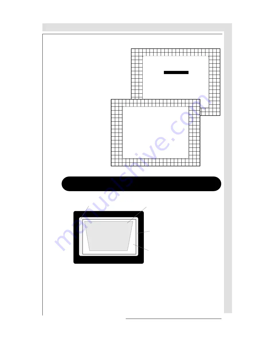
forbidden area
projected raster
crt faceplate border
phosphor border
Raster Shift Adjustment
The green raster must be
centered both horizontally and
vertically on the center of the
CRT surface. To center the
green raster, look into the green
lens and use the control disc to
move the raster.
CAUTION
It is necessary to look
into the lenses to per-
form these adjust-
ments. To avoid eye
discomfort while look-
ing into the lenses,
reduce the contrast
and gradually in-
crease the brightness
level until the raster
becomes visible on
the face of the CRT.
Warning
: In order to ensure maximum CRT longevity and to avoid CRT
damage, do not shift the raster outside the phosphor area of the CRT.
To start the adjustment, use the arrow keys to highlight Raster shift and press
ENTER
to display the coarse shift menu. Select 'Green horizontal' and adjust for
correct raster position in horizontal direction on the phosphor.
Continue with 'Green vertical', then with 'Red vertical' and with 'Blue vertical' until
the rasters of the 3 tubes correctly centered on the phosphor.
Select with
ê
or
é
then <ENTER>
<EXIT> to return.
GEOMETRY
H PHASE
RASTER SHIFT
LEFT-RIGHT (E-W)
TOP-BOTTOM (N-S)
H SIZE
V LINEARITY
V SIZE
BLANKING
COARSE SHIFT
GREEN HORIZONTAL
GREEN VERTICAL
RED VERTICAL
BLUE VERTICAL
Select with
ê
or
é
<ENTER> to accept
<EXIT> to return.
forbidden area
projected raster
crt faceplate border
phosphor border
Summary of Contents for R9002327
Page 15: ...SAFETYINSTRUCTIONS SAFETY INSTRUCTIONS 1 8 R5975059ABARCOVISION708 200498...
Page 22: ...R5975059ABARCOVISION708 200498 POWERCONNECTION POWER CONNECTION 3 1 POWER MAINS CONNECTION...
Page 47: ...CONTROLLING CONTROLLING R5975059ABARCOVISION708 200498 5 12...
Page 143: ...APPENDIX B ORBITING APPENDIX B ORBITING R5975059ABARCOVISION708 200498 B 6...
Page 149: ...APPENDIXC CONTRASTMODULATION R5975059ABARCOVISION708 200498 APPENDIX C CONTRAST MODULATION C 6...


