background image

Manual 2100-458C
Page

4 of 17

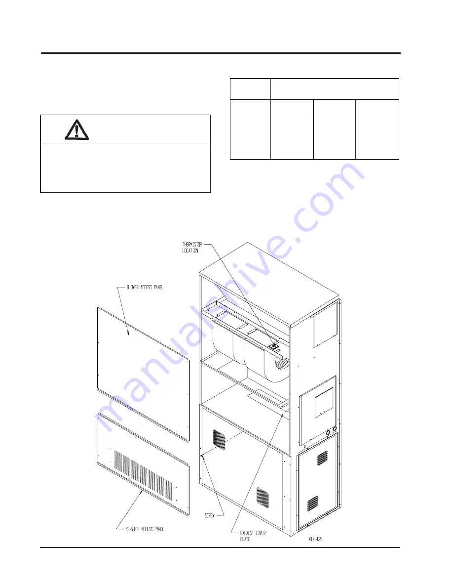
2. Remove and save the existing exterior blower

access and service access panels on the Bard wall
mount unit.  (See Figure 1.)

INSTALLATION

BASIC INSTALLATION

1. Unpack the ventilator assembly which includes the

integral ventilator with attached electrical harness
and miscellaneous hardware.

         WARNING

Open and lock unit disconnect switch before
installing this accessory to prevent injury or
death due to electrical shock or contact with
moving parts.  Turn thermostat to off.

L

E

D

O

M

H

T

I

W

E

S

U

R

O

F

S

T

I

N

U

G

N

I

W

O

L

L

O

F

5

-

S

V

R

C

5

-

P

V

R

C

2

4

A

W

8

4

A

W

0

6

A

W

2

4

H

W

8

4

H

W

0

6

H

W

8

3

H

S

3

4

H

S

9

4

H

S

1

6

H

S

2

4

L

W

8

4

L

W

0

6

L

W

TABLE 1

FIGURE  1

REMOVAL OF EXTERIOR PANELS

Summary of Contents for CRVS-5

Page 1: ...5 For Use with Bard 3 1 2 through 5 Ton Wall Mount Air Conditioners and Heat Pumps Copyright 2004 Manual 2100 458C Supersedes 2100 458B File Volume III Tab 19 Date 08 18 06 Bard Manufacturing Company...

Page 2: ...ll Ventilator 7 Figure 5 Top View of Control Panel 8 Figure 5A 9 Figure 5B 9 Figure 6 CRVS Position Adjustment 10 Figure 7 Call for Blower Operation 16 Figure 8 Call for Cooling Operation 17 Tables Ta...

Page 3: ...it is received and before signing the freight bill verify that all items have been received and that there is no visible damage Note any shortages or damage on all copies of the freight bill The rece...

Page 4: ...ttached electrical harness and miscellaneous hardware WARNING Open and lock unit disconnect switch before installing this accessory to prevent injury or death due to electrical shock or contact with m...

Page 5: ...458C Page 5 of 17 FIGURE 2 REMOVAL OF AIR FILTER AND EXHAUST COVER PLATE 3 Remove and save existing unit air filter and screws from front center grille See Figure 2 4 Remove and discard the exhaust c...

Page 6: ...to the right until it is tight against the back of the control panel See Figure 4 5 For Installation of Left Hand Units Only Remove strain relief in right side of CRV Unclip the 2 wire ties holding th...

Page 7: ...s leads through the 7 8 bushing in control panel Figure 4 into low voltage box FIGURE 4 INSTALL VENTILATOR IMPORTANT Position front lip of ventilator on top of front grille and condenser partition See...

Page 8: ...n throughout travel to assure free unobstructed movement See Figure 5 E De energize evaporator blower Damper blade should close G This completes ventilator checkout 14 Adjust damper blade for required...

Page 9: ...380 BR W 2 C RC R G Y W 2 CRVP W3 A1 C RC R G Y W W2 Y2 O C R G Y W1 W2 E F 1 2 3 1 R 4 4 BK 3 CRVS C R G Y1 W1 W2 Y2 MIS 2174 A FACTORY INSTALLED JUMPER 1 4 3 WIRE USED ON CRVP ONLY WHEN THE CRV IS...

Page 10: ...he following pages to determine the blade setting necessary to achieve the ventilation air required With the blower energized use the thumbwheel on the CRVS 5 adjust blade to desired blade position On...

Page 11: ...fm Total Air 0 ESP Total Air 2 ESP Vent Air 0 ESP Vent Air 2 ESP SH381 MEDIUM SPEED TOTAL AND VENTILATION AIRFLOW SH381 HIGH SPEED TOTAL AND VENTILATION AIRFLOW 0 100 200 300 400 500 600 700 800 900 1...

Page 12: ...ESP Total Air 2 ESP Vent Air 0 ESP Vent Air 2 ESP SH381 LOW SPEED TOTAL AND VENTILATION AIRFLOW 0 100 200 300 400 500 600 700 800 900 1000 1100 1200 1300 1400 1500 1600 1700 1800 A B C D E F Vent Pos...

Page 13: ...2000 2100 A B C D E F Vent Position Airflow cfm Total Air 0 ESP Total Air 2 ESP Total Air 4 ESP Vent Air 0 ESP Vent Air 2 ESP Vent Air 4 ESP SH431 SH491 SH611 MEDIUM SPEED TOTAL AND VENTILATION AIRFL...

Page 14: ...n Airflow cfm Total Air 0 ESP Total Air 2 ESP Total Air 4 ESP Vent Air 0 ESP Vent Air 2 ESP Vent Air 4 ESP WA WH60 HIGH SPEED TOTAL AND VENTILATION AIRFLOW 0 100 200 300 400 500 600 700 800 900 1000 1...

Page 15: ...W SPEED TOTAL AND VENTILATION AIRFLOW 0 100 200 300 400 500 600 700 800 900 1000 1100 1200 1300 1400 1500 1600 A B C D E F Vent Position Airflow cfm Total Air 0 ESP Total Air 2 ESP Total Air 4 ESP Ven...

Page 16: ...st air damper built in with positive closed position Provides exhaust air capability to prevent pressurization of tight buildings Actuator motor 24 volt power open spring return with built in torque l...

Page 17: ...al 2100 458C Page 17 of 17 A call for cooling cycles the compressor and dampers remain in the ventilation mode On loss of blower operation CRV closes fully See Figure 8 FIGURE 8 CALL FOR COOLING OPERA...

Reviews: