Manual 2100-760
Page
7 of 17
7. Open control panel to gain access to unit low
voltage terminal block.
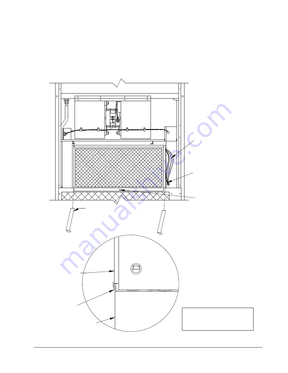
8. Route electrical harness leads through the 7/8"
bushing in control panel into low voltage box as
shown in Figure 4.
FIGURE 4
Install Ventilator
IMPORTANT:
Position front lip of ventilator on
top of front grille and condenser partition (see
Figure 4 inset). This is important to ensure
proper drainage of any water entering damper
assembly.
Note:
When installing CRV
position so hole in front
Plug the (4) Ø.125 holes
in the service door with
insert a self drilling screw.
WIRES
in condenser grille to
lip is centered over hole
CRV in unit
Right side of
Route the pink, purple,
grille and service door
MIS-2030 A
Lip of CRV is to be
canoe clips.
Service Door
with doors
removed
Front Grille
Front of unit
between the condenser
the upper grommet.
and black wires through
Place the provided ventilator slides
in the unit and position the vent package sides
on top of them. Use these to slide the vent into
the unit. Ventilator slides should be removed
after installation.


