Manual 2100-435D
Page
12 of 38
FRESH AIR INTAKE
This unit is equipped with a fresh air damper assembly.
The damper blade is locked in the closed position when
the unit is shipped from the Factory. To allow the
damper to operate remove the two plastic locking pins,
one on each end of the blade. This will allow for
maximum fresh air flow. The damper blade will now
open when the indoor blower is operating. If less than
maximum fresh air flow is required, reinsert the plastic
pins to limit damper blade opening to desired level.
Two extra pins are provided (taped to the inside of the
assembly) which may be used to hold the blade in some
position other than minimum or maximum position.
This fresh air assembly is located in the rear of the unit
and to gain access to make these adjustments remove
the air filter service door.
All capacity, efficiency and cost of operation
information as required for Department of Energy
“Energyguide” Fact Sheets are based upon the fresh air
blank-off plate in place and is recommended for
maximum energy efficiency.
The blank-off plate is available upon request from the
factory and is installed in place of the fresh air damper
shipped with each unit.
For details on energy recovery ventilation see separate
section.
CONDENSATE DRAIN
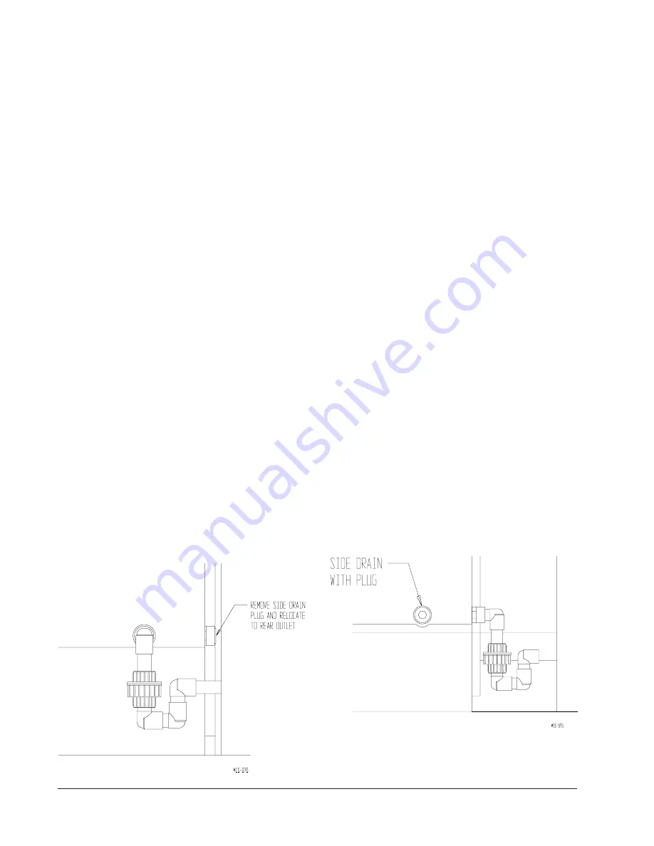
There are two drain connections on the unit. The rear
drain is the primary drain, and is located on the right
lower rear panel of the unit. The optional side drain is
located on the bottom right side of the unit. The side
drain is shipped with a plug installed.
The
side drain
requires a water trap for proper drainage.
See Figure 9. The drain can be routed through the floor
or through the wall.
If the drain is to be routed
through an unconditioned space, it must be protected
from freezing.
The drain line must be able to be
removed from the unit if it is necessary to remove the
unit from the wall. When the side drain is used, the plug
must be removed and installed in the rear drain outlet.
The
rear drain
can be used with wall thickness of up to
10 inches where a water trap can be installed between
the unit and the interior wall. See Figure 10. The trap
cannot extend beyond the edge of the unit or it will
interfere with the wall mounting bracket. The drain can
be routed through the floor or through the wall. If the
drain is routed through the wall, the drain line must be
positioned such that it will not interfere with the sleeve
flange or the grille. See Figure 11.
If the drain is to be
routed through an unconditioned space, it must be
protected from freezing.
Optional rear drain kits, both standard and heated
versions, are available to facilitate easy installation, and
also removability of heat pump for service.
FIGURE 9
OPTIONAL SIDE DRAIN (SIDE VIEW)
INSTALLATION
QT
EC
UNIT
FIGURE 10
STANDARD REAR DRAIN
Summary of Contents for QTEC QH303D
Page 7: ...Manual 2100 435D Page 7 of 38 FIGURE 1 UNIT DIMENSIONS...
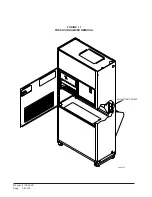
Page 26: ...Manual 2100 435D Page 26 of 38 MIS 1627 FIGURE 17 FRESH AIR DAMPER REMOVAL MOUNTING SCREW...
Page 30: ...Manual 2100 435D Page 30 of 38 FIGURE 20 QTEC DEHUMIDIFICATION MODE CIRCUIT DIAGRAM MIS 1088...
Page 31: ...Manual 2100 435D Page 31 of 38 FIGURE 21 QTEC COOLING MODE CIRCUIT DIAGRAM MIS 1089...


