Manual 2100-435D
Page
22 of 38
RAT
C
R
E1
BK
TWV
YO
A2
Y
B
L
L
E1
G1
RV
W
A1
W2
G
D
Relay Logic Board
Return Air
Thermostat
Plug #2
Purple
Red
Yellow
Orange
Tan
Yellow
Black
Brown
Blue
Yellow
Orange
Tan
Orange
Red
Red
Red
Red
Black
Black
Black
Red
2
3
1
2
3
4
5
6
7
8
9
10
11
12
Y1
G
7
6
5
4
3
2
1
Plug #4
8
B
W2
R
C
L
12
11
10
9
Brown
Blue
W1
4
3
5
6
Blue
Red
Red
Yellow
Tan
Orange
Yellow
Blue
Brown
Red
Black
H200
Humidistat
T8511
Thermostat
Yellow
E
C
Y1
Y
O1
Terminal
Block #1
Black
Red
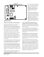
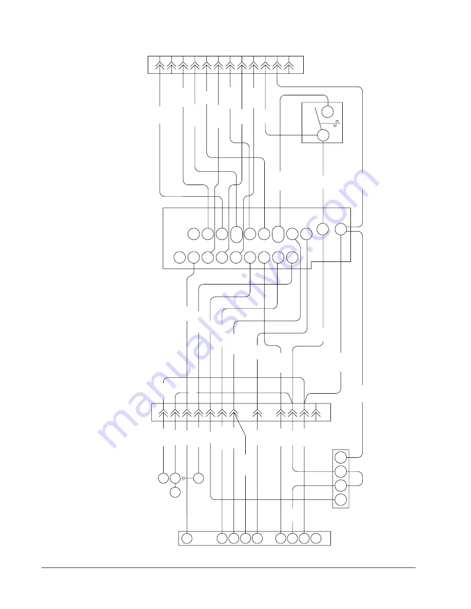
FIGURE 16C
UNIT MOUNTED THERMOSTAT AND HUMIDISTAT WIRING DIAGRAM
“G” THERMOSTAT OPTION
DEHUMIDIFICATION MODULE
NOTE: On options X and G the CS2000A (or other field provided means to control ventilation)
must be used if any of the mechanical (motorized) ventilation options are installed.
4102-039
Summary of Contents for QTEC QH303D
Page 7: ...Manual 2100 435D Page 7 of 38 FIGURE 1 UNIT DIMENSIONS...
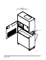
Page 26: ...Manual 2100 435D Page 26 of 38 MIS 1627 FIGURE 17 FRESH AIR DAMPER REMOVAL MOUNTING SCREW...
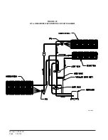
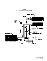
Page 30: ...Manual 2100 435D Page 30 of 38 FIGURE 20 QTEC DEHUMIDIFICATION MODE CIRCUIT DIAGRAM MIS 1088...
Page 31: ...Manual 2100 435D Page 31 of 38 FIGURE 21 QTEC COOLING MODE CIRCUIT DIAGRAM MIS 1089...


