Manual
2100-435D
Page
25 of 38
VENT OPTIONS
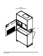
BAROMETRIC FRESH AIR DAMPER (Standard)
Before starting, make sure the power has been turned
off. The return air grille panel must be removed. The
fresh air damper assembly can be seen on the back of
the unit. See Figure 17.
1. The fresh air damper is attached to the back of the
unit with one screw on either side of the
assembly. Both of the screws must be removed.
2. Once the mounting screws are removed, tilt the
assembly down and lift it out.
The mist eliminator can be seen through the opening.
The mist eliminator must be raised up and the bottom
can be pulled toward the front of the unit.
COMMERCIAL ROOM VENTILATOR (Option)
Before starting, make sure the power has been turned
off. The return air grille panel must be removed. The
commercial room ventilator (CRV) can be seen after the
panel has been removed. The CRV must be remove to
gain access to the mist eliminator.
1. The two mounting screws in the front of the CRV
must be removed.
2. The power connectors for the CRV (located on
the right side of the unit) must be disconnected.
Squeeze the tabs on the sides of the connector
and pull straight out. Unplug both of the
connectors.
3. Slide the CRV straight out of the unit.
The mist eliminator can be seen through the opening in
the back of the unit. The mist eliminator must be raised
up and the bottom can be pulled toward the front of the
unit and removed.
QT
EC
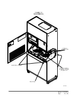
R ENERGY RECOVERY VENTILATOR
(Option)
Before starting, make sure that the power has been
turned off. The return air grille panel must be removed.
The energy recovery ventilator (QERV) can be seen
after the panel has been removed. To gain access to the
mist eliminator, the QERV must be removed. See
Figure 18.
1. The front fill plate of the QERV must be
removed. There is one screw on either side of the
plate. Remove these screws and remove the
plate.
2. On either side of the QERV there are mounting
screws that hold the QERV in place. Remove
both of these screws.
3. Underneath the heat recovery cassette there is a
power connector for the lower blower assembly.
To disconnect this plug, the tabs on both sides of
the plug must be squeezed to release the plug.
While squeezing the tabs, pull the plug out of the
socket.
4. The QERV is plugged into the unit in the right
side of the unit. Both of these plugs must be
disconnected to remove the QERV. Squeeze the
tabs on the sides of the connector and pull
straight out.
5. Slide the QERV assembly straight out of the unit,
being careful not to let the cassette slide out of
the QERV.
The mist eliminator can be seen through the opening in
the back of the unit. The mist eliminator must be raised
up and the bottom can be pulled toward the front of the
unit and removed.
Summary of Contents for QTEC QH303D
Page 7: ...Manual 2100 435D Page 7 of 38 FIGURE 1 UNIT DIMENSIONS...
Page 26: ...Manual 2100 435D Page 26 of 38 MIS 1627 FIGURE 17 FRESH AIR DAMPER REMOVAL MOUNTING SCREW...
Page 30: ...Manual 2100 435D Page 30 of 38 FIGURE 20 QTEC DEHUMIDIFICATION MODE CIRCUIT DIAGRAM MIS 1088...
Page 31: ...Manual 2100 435D Page 31 of 38 FIGURE 21 QTEC COOLING MODE CIRCUIT DIAGRAM MIS 1089...


