Manual 2100-435D
Page
34 of 38
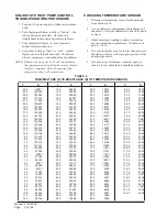
CHECKING TEMPERATURE SENSOR
1. Disconnect temperature sensor from board and
from outdoor coil.
2. Use an ohmmeter and measure the resistance of
the sensor. Also use ohmmeter to check for short
or open.
3. Check resistance reading to chart of resistance
use sensor ambient temperature. (Tolerance of
part is ± 10%.)
4. If sensor resistance reads very low, then sensor is
shorted and will not allow proper operation of the
heat pump control.
5. If sensor is out of tolerance, shorted, open, or
reads very low ohms then it should be replaced.
SOLID STATE HEAT PUMP CONTROL
TROUBLESHOOTING PROCEDURE
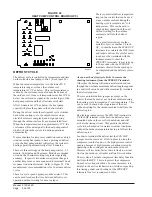
1. Turn on AC power supply to indoor and outdoor
units.
2. Turn thermostat blower switch to “fan on” – the
indoor blower should start. (If it doesn’t,
troubleshoot indoor unit and correct problem.)
3. Turn thermostat blower to “auto” position.
Indoor blower should stop.
4. Set system switch to “heat” or “cool”. Adjust
thermostat to call for heat or cool. The indoor
blower, compressor and outdoor fan should start.
NOTE: If there was no power to 24 volt transformer,
the compressor and outdoor fan motor will not
start for 5 minutes. This is because of the
compressor short cycle protection.
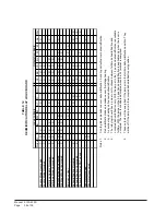
TABLE 6
TEMPERATURE (F) VS RESISTANCE (R) OF TEMPERATURE SENSOR
F
R
F
R
F
R
F
R
0
.
5
2
-
0
.
4
2
-
0
.
3
2
-
0
.
2
2
-
0
.
1
2
-
0
.
0
2
-
0
.
9
1
-
0
.
8
1
-
0
.
7
1
-
0
.
6
1
-
0
.
5
1
-
0
.
4
1
-
0
.
3
1
-
0
.
2
1
-
0
.
1
1
-
0
.
0
1
-
0
.
9
-
0
.
8
-
0
.
7
-
0
.
6
-
0
.
5
-
0
.
4
-
0
.
3
-
0
.
2
-
0
.
1
-
0
.
0
0
.
1
0
.
2
0
.
3
0
.
4
0
.
5
0
.
6
0
.
7
0
.
8
0
.
9
0
.
0
1
0
.
1
1
0
.
2
1
1
7
8
6
9
1
9
9
0
0
9
1
5
8
5
3
8
1
8
1
3
7
7
1
9
8
2
1
7
1
7
8
4
5
6
1
4
0
9
9
5
1
9
2
5
4
5
1
5
5
3
9
4
1
4
7
3
4
4
1
6
7
5
9
3
1
6
5
9
4
3
1
6
0
5
0
3
1
9
1
2
6
2
1
9
8
0
2
2
1
8
0
1
8
1
1
2
7
2
4
1
1
5
7
5
0
1
1
0
1
0
7
0
1
4
7
5
3
0
1
0
6
2
0
0
1
4
6
0
7
9
1
8
9
3
9
8
0
0
1
9
9
3
1
8
8
1
7
3
5
8
9
9
6
2
8
1
2
1
0
8
2
3
6
7
7
0
3
2
5
7
0
1
9
2
7
0
7
6
0
7
7
0
5
8
6
8
1
4
6
6
9
9
3
4
6
9
4
4
2
6
5
6
5
0
6
5
4
7
8
5
0
.
3
1
0
.
4
1
0
.
5
1
0
.
6
1
0
.
7
1
0
.
8
1
0
.
9
1
0
.
0
2
0
.
1
2
0
.
2
2
0
.
3
2
0
.
4
2
0
.
5
2
0
.
6
2
0
.
7
2
0
.
8
2
0
.
9
2
0
.
0
3
0
.
1
3
0
.
2
3
0
.
3
3
0
.
4
3
0
.
5
3
0
.
6
3
0
.
7
3
0
.
8
3
0
.
9
3
0
.
0
4
0
.
1
4
0
.
2
4
0
.
3
4
0
.
4
4
0
.
5
4
0
.
6
4
0
.
7
4
0
.
8
4
0
.
9
4
0
.
0
5
5
8
9
6
5
4
8
2
5
5
0
4
6
3
5
1
5
0
2
5
4
1
5
0
5
8
2
0
9
4
0
9
5
7
4
0
0
2
6
4
5
5
8
4
4
4
5
5
3
4
5
9
2
2
4
7
7
0
1
4
8
9
8
9
3
7
5
7
8
3
2
5
6
7
3
3
8
5
6
3
8
4
5
5
3
5
4
5
4
3
4
7
5
3
3
4
3
6
2
3
3
2
7
1
3
0
4
8
0
3
6
8
9
9
2
7
5
1
9
2
5
5
3
8
2
7
7
5
7
2
3
2
8
6
2
2
9
0
6
2
3
8
3
5
2
6
9
6
4
2
0
3
0
4
2
4
8
3
3
2
8
5
7
2
2
0
5
1
2
2
1
6
5
1
2
9
8
9
0
2
5
3
4
0
2
6
9
8
9
1
0
.
3
5
0
.
2
5
0
.
3
5
0
.
4
5
0
.
5
5
0
.
6
5
0
.
7
5
0
.
8
5
0
.
9
5
0
.
0
6
0
.
1
6
0
.
2
6
0
.
3
6
0
.
4
6
0
.
5
6
0
.
6
6
0
.
7
6
0
.
8
6
0
.
9
6
0
.
0
7
0
.
1
7
0
.
2
7
0
.
3
7
0
.
4
7
0
.
5
7
0
.
6
7
0
.
7
7
0
.
8
7
0
.
9
7
0
.
0
8
0
.
1
8
0
.
2
8
0
.
3
8
0
.
4
8
0
.
5
8
0
.
6
8
0
.
7
8
0
.
8
8
4
7
3
9
1
7
6
8
8
1
5
7
3
8
1
9
8
9
7
1
4
3
4
7
1
4
8
9
6
1
7
4
5
6
1
2
2
1
6
1
0
1
7
5
1
0
1
3
5
1
1
2
9
4
1
4
4
5
4
1
7
7
1
4
1
0
2
8
3
1
4
7
4
3
1
7
3
1
3
1
0
1
8
2
1
2
9
4
2
1
3
8
1
2
1
3
8
8
1
1
1
9
5
1
1
7
0
3
1
1
1
3
0
1
1
2
6
7
0
1
1
0
5
0
1
7
4
2
0
1
0
0
0
0
1
0
6
7
9
6
2
5
9
9
9
2
9
7
7
0
9
2
6
8
8
3
5
6
8
9
4
4
8
0
5
2
8
7
5
0
8
9
6
8
7
6
8
6
7
0
.
9
8
0
.
0
9
0
.
1
9
0
.
2
9
0
.
3
9
0
.
4
9
0
.
5
9
0
.
6
9
0
.
7
9
0
.
8
9
0
.
9
9
0
.
0
0
1
0
.
1
0
1
0
.
2
0
1
0
.
3
0
1
0
.
4
0
1
0
.
5
0
1
0
.
6
0
1
0
.
7
0
1
0
.
8
0
1
0
.
9
0
1
0
.
0
1
1
0
.
1
1
1
0
.
2
1
1
0
.
3
1
1
0
.
4
1
1
0
.
5
1
1
0
.
6
1
1
0
.
7
1
1
0
.
8
1
1
0
.
9
1
1
0
.
0
2
1
0
.
1
2
1
0
.
2
2
1
0
.
3
2
1
0
.
4
2
1
7
0
5
7
4
3
3
7
5
6
1
7
0
0
0
7
0
4
8
6
3
8
6
6
1
3
5
6
3
8
3
6
9
3
2
6
8
9
0
6
1
6
9
5
7
2
8
5
7
9
6
5
0
7
5
5
6
4
4
5
6
2
3
5
8
0
2
5
4
9
0
5
2
8
9
4
3
7
8
4
7
6
7
4
3
6
6
4
2
6
5
4
4
6
4
4
7
6
3
4
4
7
2
4
2
8
1
4
3
9
0
4
6
0
0
4
1
2
9
3
8
3
8
3
7
5
7
3
8
7
6
3
1
0
6
3
6
2
5
3
2
5
4
3
Summary of Contents for QTEC QH303D
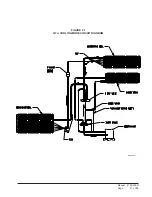
Page 7: ...Manual 2100 435D Page 7 of 38 FIGURE 1 UNIT DIMENSIONS...
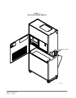
Page 26: ...Manual 2100 435D Page 26 of 38 MIS 1627 FIGURE 17 FRESH AIR DAMPER REMOVAL MOUNTING SCREW...
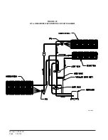
Page 30: ...Manual 2100 435D Page 30 of 38 FIGURE 20 QTEC DEHUMIDIFICATION MODE CIRCUIT DIAGRAM MIS 1088...
Page 31: ...Manual 2100 435D Page 31 of 38 FIGURE 21 QTEC COOLING MODE CIRCUIT DIAGRAM MIS 1089...


