background image

Manual 2100-435D
Page

8 of 38

SHIPPING DAMAGE

Upon receipt of equipment, the carton should be
checked for external signs of shipping damage.  The
skid must remain attached to the unit until the unit is
ready for installation.  If damage is found, the receiving
party must contact the last carrier immediately,
preferably in writing, requesting inspection by the
carrier’s agent.

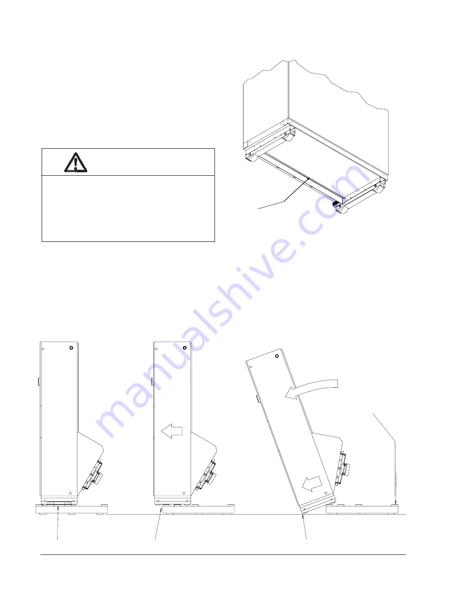
UNIT REMOVAL FROM SKID

FIGURE   3

REMOVAL OF UNIT FROM SKID

A  Shipping Brackets

B  Front Wheels Over Edge

C  Front Wheels On Floor

Hold Skid Down

It is recommended that the unit not be removed from
the skid with a fork lift since the air seal under the unit
could be damaged.  See Figure 2.

The shipping brackets on each side of the unit must be
removed and discarded.  See Figure 3-A.  The return air
grille panel can be removed to provide a place to hold

the unit.  The unit can be slid forward on the skit until
the front wheels hang over the edge of the skid.  See
Figure 3-B. The unit can be tipped forward and slid
down the edge of the skid until the front wheels touch
the ground.  See Figure 3-C.  The wheels will not roll.
They are shipped from the factory locked so they will
not roll.  The back of the skid will have to be held down
to keep it from tipping up.  The skid can be slid out from
under the unit.  The unit can then be set upright.

        WARNING

This unit is heavy and requires more than one
person to handle and remove from the skid.
Check unit wheels to ensure that wheels are
locked before removing from skid.  Extreme
caution must be taken to prevent injury to
personnel and damage to the unit.

MIS-1007

FIGURE 2

AIR SEAL UNDER QT

EC

 UNIT

MIS-1008

Air Seal

Summary of Contents for QTEC QH303D

Page 1: ...QH423D QH483D QH603D QTEC SERIES PACKAGED HEAT PUMP INSTALLATION INSTRUCTIONS Bard Manufacturing Company Bryan Ohio 43506 Since 1914 Moving ahead just as planned Manual 2100 435D Supersedes 2100 435C...

Page 2: ...ation 23 Service Hints 24 Mist Eliminator Service 24 Vent Options 25 Sequence of Operation 28 Optional Climate Controls Sequence of Operation 28 Refrigerant Tube Schematic for Reheat Coil 29 Pressure...

Page 3: ...mer Manual N Air Conditioning Low Pressure Low Velocity ACCA Manual D or Duct System Design Manual Q Winter and Summer Air Conditioning FOR MORE INFORMATION CONTACT THESE PUBLISHERS ACCA Air Condition...

Page 4: ...otorized w Exhaust Spring Return FILTER OPTIONS X 1 Inch Fiberglass Standard F 2 Inch Fiberglass P 2 Inch Pleated COLOR OPTIONS V Platinum w Slate Front Vinyl 4 Gray paint TABLE 1 FACTORY BUILT IN ELE...

Page 5: ...R E W O P E R I W E Z I S 2 D N U O R G E R I W E Z I S 3 M U M I N I M T I U C R I C Y T I C A P M A 1 M U M I X A M L A N R E T X E R O E S U F T I U C R I C R E K A E R B 2 D L E I F R E W O P E Z...

Page 6: ...Z 0 B D 3 8 4 H Q 6 0 B D 9 0 B D 5 5 1 B D 3 8 0 2 0 3 2 1 1 1 1 6 2 4 4 3 5 3 5 0 4 0 5 0 6 0 6 8 8 6 6 0 1 0 1 0 1 0 1 Z 0 C D 3 8 4 H Q 6 0 C D 9 0 C D 5 5 1 C D 3 0 6 4 1 1 1 1 4 1 3 2 7 2 7 2 5...

Page 7: ...Manual 2100 435D Page 7 of 38 FIGURE 1 UNIT DIMENSIONS...

Page 8: ...e removed and discarded See Figure 3 A The return air grille panel can be removed to provide a place to hold the unit The unit can be slid forward on the skit until the front wheels hang over the edge...

Page 9: ...ructions packaged with any separate equipment required to make up the entire air conditioning system should be carefully read before beginning the installation Note particularly Start Procedure and an...

Page 10: ...NG 8 FT 6 IN MINIMUM RECOMMENDED CEILING HEIGHT 8 FT 5 IN FLOOR MIS 1573 SUSPENDED CEILING FIXED CEILING DUCT DUCT FLANGE 8 FT 7 IN MINIMUM RECOMMENDED CEILING HEIGHT 7 FT 4 IN UNIT HEIGHT 12 IN MINIM...

Page 11: ...free blow with the use of QPB Plenum Box or a duct supply air system For hot water coil options a QPBHW F for free blow or QPBHW D for ducted airflow is used The QPB and QPBHW Plenum Box mounts on top...

Page 12: ...nnections on the unit The rear drain is the primary drain and is located on the right lower rear panel of the unit The optional side drain is located on the bottom right side of the unit The side drai...

Page 13: ...ice This indicates that the unit needs to be serviced MIS 1061 FIGURE 12 UNIT MOUNTING BOTTOM TRIM PIECE BOTTOM TRIM EXTENSION MOUNTING BRACKET SIDE TRIM 2 PCS SIDE TRIM 2 PCS MIS 1576 CABINET SIDE PA...

Page 14: ...keep it centered in the sleeve Also check the alignment to the mounting brackets This unit must be level from side to side If adjustments are necessary shim up under the rollers with sheets of steel o...

Page 15: ...that amount of current Depending on the installed KW of electric heat there may be two field power circuits required If this is the case the unit serial plate will so indicate All models are suitable...

Page 16: ...under Emergency Heat conditions where the compressor needs to be deactivated the B W2 E outputs need to be energized Removing the Y compressor signal alone turns the compressor off but does not activa...

Page 17: ...S s e r u t a e F t n a n i m o d e r P 8 1 0 3 0 4 8 4 2 0 1 N 4 7 8 T 0 1 0 4 0 4 8 1 6 2 1 4 7 6 Q 2 l o o C t a e H c i t a m o t u A n o i t i s o P r e v o e g n a h C 8 3 0 3 0 4 8 A 0 0 6 H A...

Page 18: ...3 4 5 6 7 8 9 10 11 12 Y1 G E 7 6 5 4 3 2 1 Plug 4 8 B W2 R C L 12 11 10 9 Brown Blue W1 W1 Y1 W1 L C R W2 L C R W2 B B E1 G A1 Y1 4 3 5 6 Y G O1 4 E 5 6 Blue Red Red Yellow Tan Orange Yellow Blue Br...

Page 19: ...ns to control ventilation must be used if any of the mechanical motorized ventilation options are installed DEHUM CIRCUIT 24 VAC COM DEHUM CIRCUIT COMPRESSOR NOTE FIELD SUPPLIED DEHUMIDISTAT MUST BE D...

Page 20: ...n Blue Yellow Orange Tan Orange Red Red Red Red Black Black Black Red 2 3 1 2 3 4 5 6 7 8 9 10 11 12 7 6 5 4 3 2 1 Plug 4 8 12 11 10 9 Brown Blue W1 L C R W2 B E1 G A1 Y1 Blue Red Red Tan Orange Yello...

Page 21: ...n Blue Yellow Orange Tan Orange Red Red Red Red Black Black Black Red 2 3 1 2 3 4 5 6 7 8 9 10 11 12 Y1 G 7 6 5 4 3 2 1 Plug 4 8 B W2 R C L 12 11 10 9 Brown Blue W1 4 3 5 6 Blue Red Red Yellow Tan Ora...

Page 22: ...4 3 2 1 Plug 4 8 B W2 R C L 12 11 10 9 Brown Blue W1 4 3 5 6 Blue Red Red Yellow Tan Orange Yellow Blue Brown Red Black H200 Humidistat T8511 Thermostat Yellow E C Y1 Y O1 Terminal Block 1 Black Red...

Page 23: ...nitor to prevent compressor damage due to phase reversal The phase monitor in this unit is equipped with two LEDs If the Y signal is present at the phase monitor and phases are correct the green LED w...

Page 24: ...cabinet side panel g Remove screws that attach the duct work to the unit flanges This unit is equipped with four rollers mounted to the base For ease of pulling unit out from the wall you may want to...

Page 25: ...h the opening in the back of the unit The mist eliminator must be raised up and the bottom can be pulled toward the front of the unit and removed QTEC R ENERGY RECOVERY VENTILATOR Option Before starti...

Page 26: ...Manual 2100 435D Page 26 of 38 MIS 1627 FIGURE 17 FRESH AIR DAMPER REMOVAL MOUNTING SCREW...

Page 27: ...Manual 2100 435D Page 27 of 38 MIS 1039 FIGURE 18 QERV REMOVAL MOUNTING SCREWS FRONT FILL LOWER BLOWER ASSEMBLY POWER CONNECTOR POWER CONNECTORS...

Page 28: ...ion can be restored by turning of the main power supply off and then back on or reset the room thermostat The low pressure control has a bypass to eliminate nuisance lockout on cold start up The bypas...

Page 29: ...humidity is above the setpoint of the humidistat the compressor circuit and the 3 way valve are energized and the evaporator air flow is reduced The 3 way valve directs hot discharge gas into a separa...

Page 30: ...Manual 2100 435D Page 30 of 38 FIGURE 20 QTEC DEHUMIDIFICATION MODE CIRCUIT DIAGRAM MIS 1088...

Page 31: ...Manual 2100 435D Page 31 of 38 FIGURE 21 QTEC COOLING MODE CIRCUIT DIAGRAM MIS 1089...

Page 32: ...a 0 coil temperature This can be used to check defrost operation of the unit without waiting for the outdoor ambient to fall into the defrost region Use a small screwdriver or other metallic object o...

Page 33: ...p a c d e t r o h s r o n e p o r o t i c a p a c e c a l p e R l o r t n o c p m u p t a e H e v i t c e f e d t a e h n o y a l e r n a f s s o r c a k c e h C l o r t n o c p m u p C N m o C l o r...

Page 34: ...3 9 8 0 0 1 9 9 3 1 8 8 1 7 3 5 8 9 9 6 2 8 1 2 1 0 8 2 3 6 7 7 0 3 2 5 7 0 1 9 2 7 0 7 6 0 7 7 0 5 8 6 8 1 4 6 6 9 9 3 4 6 9 4 4 2 6 5 6 5 0 6 5 4 7 8 5 0 3 1 0 4 1 0 5 1 0 6 1 0 7 1 0 8 1 0 9 1 0 0...

Page 35: ...ing performance will occur with a refrigerant charge resulting in a Super Heat as shown in Table 8 If correct charge is in doubt recover the refrigerant and recharge per the charge on the unit rating...

Page 36: ...L e d i S h g i H 4 7 2 1 2 4 7 5 1 2 5 7 3 3 2 6 7 1 5 2 7 7 9 6 2 8 7 7 8 2 9 7 5 0 3 0 8 3 2 3 1 8 1 4 3 B D g e d 0 8 B W g e d 7 6 e d i S w o L e d i S h g i H 9 7 9 1 2 9 7 0 2 2 0 8 9 3 2 1 8...

Page 37: ...2 2 3 6 3 H Q g e d 0 7 e d i S w o L e d i S h g i H 3 1 7 4 1 7 1 3 5 1 1 2 9 5 1 5 2 4 6 1 7 2 7 6 1 0 3 1 7 1 4 3 6 7 1 8 3 2 8 1 2 4 8 8 1 6 4 4 9 1 2 5 2 0 2 5 5 6 0 2 9 5 1 1 2 3 6 7 1 2 3 2 4...

Page 38: ...a jumper on it to choose between fulltime dehumidification and occupied dehumidification only With the jumper in the 1 2 position dehumidification is available fulltime With the jumper in the 2 3 posi...

Reviews: