Manual
2100-486D
Page
29 of 37
25. SERVICE AGENCY PROCEDURES
MAIN BURNER
Observe the main burners in operation. The flame
should be mostly “blue” with possibly a little orange
(not yellow) at the tips of the flame. The flames should
be in the center of the heat exchanger tubes and not
impinging on the heat exchanger surfaces themselves.
Observe the fire until the blower starts (there is a
normal delay period until the heat exchanger warms
up). There should be no change in the size or shape of
the flame. If there is any wavering or blowing of the
flame on blower start-up, it is an indication of a
possible leak in the heat exchanger.
26. MAINTAINING UNIT IN GOOD
WORKING ORDER
The unit should be inspected annually by a qualified
service agency.
BURNERS / HEAT EXCHANGER / FLUE GAS
PASSAGE WAYS
The burners, heat exchanger and interior flue gas
passages may be inspected using a light on small mirror
or an extension handle. Remove the screws securing
the inducer and collector box. Now inspect the upper
tubes of the heat exchanger.
Check the exterior of the heat exchanger and the
interior flue gas passages for any evidence of
deterioration due to corrosion, cracking or other causes.
If signs of sooting exist, remove the burners and clean
the heat exchanger, as required.
MIS-165
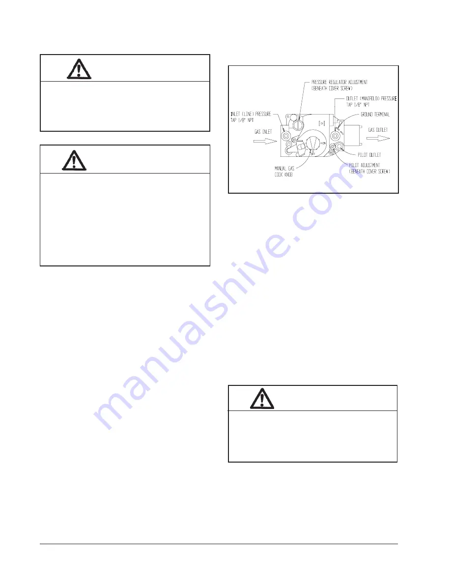
FIGURE 16
TOP VIEW OF GAS CONTROL
CAUTION
Label all wires prior to disconnection when
servicing controls. Wiring errors can cause
improper and dangerous operation. Verify
proper operation after servicing.
WARNING
Follow these procedures before inspecting
furnace.
•
Turn room thermostat to its lowest or off
setting.
•
Turn off manual gas shut off valve.
•
Wait at least 5 minutes for furnace to cool
if it was recently operating.
•
Turn off furnace electrical power; failure
to do so could result in injury or death.
WARNING
Use replacement parts listed in the
Replacement Parts list only. The use of
incorrect parts could cause improper unit
operation, resulting in damage, injury or
death.
Summary of Contents for WF0501-A
Page 13: ...Manual 2100 486D Page 13 of 37 FIGURE 6 COMMON WALL MOUNTING INSTALLATIONS...
Page 19: ...Manual 2100 486D Page 19 of 37 FIGURE 11 LOW VOLTAGE WIRING...
Page 20: ...Manual 2100 486D Page 20 of 37 FIGURE 12 GAS PIPE CONNECTION...
Page 34: ...Manual 2100 486D Page 34 of 37 230 208 60 1...
Page 35: ...Manual 2100 486D Page 35 of 37 115 60 1...


