background image

Manual

2100-486D

Page

37 of 37

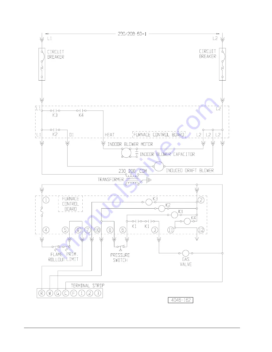
230/208-60-1

Summary of Contents for WF0501-A

Page 1: ...ng ahead just as planned WARNING READ ALL INSTRUCTIONS CAREFULLY BEFORE BEGINNING THE INSTALLATION THE INSTALLATION MUST COMPLY WITH THESE INSTRUCTIONS AND THE REQUIREMENTS OF ALL GOVERNING CODES AND...

Page 2: ...Air Intake 16 14 Wiring Main Power 17 15 Wiring Low Voltage Wiring 18 16 Thermostats 18 17 Gas Supply Piping 21 18 Manifold Pressure Adjustment 22 19 Checking Gas Input Rate 22 23 20 Standard Orifice...

Page 3: ...tion 20 Figure 13 Proper Piping Practice 21 Figure 14 Access Internal Filter through Upper Service Door 27 Figure 15 Lighting Shutdown Instruction Label 28 Figure 16 Top View of Gas Control 29 Figure...

Page 4: ...Standards Association 178 Rexdale Boulevard Rexdale Ontario Canada M9W 1R3 Telephone 416 447 4044 These publications can help you install the furnace You can usually find these at your local library o...

Page 5: ...C V 3 S V R C F W n r u t e R r e w o P r o t a l i t n e V l a i c r e m m o C P 3 P V R C F W t l o V 0 3 2 r o t a l i t n e V y r e v o c e R y g r e n E y l n O d e l l a t s n I d l e i F 3 A V...

Page 6: ...er The furnace installation must conform with local building codes and ordinances or in their absence with the National Fuel Gas Code ANSI Z223 1 or CAN CGA B149 1 latest edition and the National Elec...

Page 7: ...Q Q Q E M R Q P B I A S J L D C N G H K W U F 38 18 14 81 58 37 30 00 4 50 13 25 15 37 39 17 3 18 4 31 39 87 25 00 13 75 28 937 8 00 O A B C D E F G H I J K L M N P Q R S T U V W 5 62 12 00 4 75 2 00...

Page 8: ...bsence of specific recommendations from the local authority having jurisdiction equipment ratings shall be reduced as specified in Section 20 5 TRANSPORTATION DAMAGE All units are packed securely in s...

Page 9: ...l overhang projects above the unit See Figure 3 If a combustible wall use a minimum of Figure 1 A dimension plus 2 inches and B dimension plus 2 inches See Figures 4 and 5 for details 3 Locate and mar...

Page 10: ...UNIT RIGHT SIDE SUPPLY AIR DUCT FOUR SIDES OF SUPPLY 1 CLEARANCE ON ALL RETURN AIR DUCT CONTROL PANEL AIR DUCT IS REQUIRED FROM VESTIBULE DOOR COMBUSTABLE MATERIALS WALL STRUCTURE OUTSIDE NOTE IT IS R...

Page 11: ...ined between the supply air duct and combustible materials This is required for the first three 3 feet of ducting It is important to insure that the one 1 inch minimum spacing is maintained at all poi...

Page 12: ...Manual 2100 486D Page 12 of 37 FIGURE 4 WALL MOUNTING INSTRUCTIONS FIGURE 5 WALL MOUNTING INSTRUCTIONS...

Page 13: ...Manual 2100 486D Page 13 of 37 FIGURE 6 COMMON WALL MOUNTING INSTALLATIONS...

Page 14: ...INIMUM INSTALLATION CLEARANCES s l a i r e t a m e l b i t s u b m o c m o r f t c u D t e l t u O t e e f 3 t s r i f h c n i 1 s l a i r e t a m e l b i t s u b m o c m o r f l a n i m r e T t n e V...

Page 15: ...hang The kit includes a stainless steel transition drain tee silicone sealant and drain tubing If unit is installed with vertical vent kit annually inspect the vent system and drain Replace any portio...

Page 16: ...ing instructions Place the appliance being inspected in operation Adjust thermostat so appliance shall operate continuously 5 Test for draft hood equipped appliance spillage at the draft hood relief o...

Page 17: ...age conduit through 1 3 4 bushing located in conduit entrance plate and secure to high voltage opening in rear of control panel 5 Replace conduit access panel if required to complete installation 6 Se...

Page 18: ...r T A V A L F e g u a G e r i W m u m i x a M e c n a t s i D t e e F n I 0 4 3 2 e g u a g 0 2 e g u a g 8 1 e g u a g 6 1 e g u a g 4 1 e g u a g 2 1 5 4 0 6 0 0 1 0 6 1 0 5 2 FIGURE 10 INSTALLATIO...

Page 19: ...Manual 2100 486D Page 19 of 37 FIGURE 11 LOW VOLTAGE WIRING...

Page 20: ...Manual 2100 486D Page 20 of 37 FIGURE 12 GAS PIPE CONNECTION...

Page 21: ...0 0 0 0 5 0 5 0 0 0 6 5 0 0 0 5 1 1 0 0 0 5 1 2 0 0 0 0 4 4 0 6 0 0 0 0 5 0 0 0 5 0 1 0 0 0 5 9 1 0 0 0 0 0 4 0 7 0 0 0 6 4 0 0 0 6 9 0 0 0 0 8 1 0 0 0 0 7 3 0 8 0 0 0 3 4 0 0 0 0 9 0 0 0 0 7 1 0 0 0...

Page 22: ...ese kits may be purchased from your local distributor 5 Slowly open equipment shut off valve in gas supply line just ahead of furnace Start furnace following Operating Instructions on front door 6 Slo...

Page 23: ...the furnace gas input PROPANE LP GAS INPUT RATE 1 Make sure you have proper main burner orifices 2 Gas supply pressure must be between 11 and 13 inches W C for propane LP gas 3 Start furnace followin...

Page 24: ...6 0 5 7 0 6 0 0 5 7 6 6 0 8 8 5 0 4 3 5 6 2 6 8 6 5 0 8 1 3 6 8 1 9 4 5 0 2 0 1 6 0 6 4 3 5 0 0 4 9 5 8 8 4 2 5 0 2 3 8 5 3 7 2 1 5 0 7 9 6 5 4 4 5 0 5 0 6 1 6 5 2 7 5 9 4 0 8 0 5 5 5 6 9 8 4 5 0 4 4...

Page 25: ...F 0 0 0 0 1 o t 1 0 0 8 h c t i w S e r u s s e r P s e r i u q e R e c i f i r O d n a e g n a h C e g n a h C t n e t n o C U T B n o d e s a B U T B 0 0 5 2 2 r e n r u B r e P 9 4 7 0 0 7 5 7 2 0...

Page 26: ...oximately 2 feet from furnace Locate thermometer tip in center of plenum to insure proper temperature measurement 6 Place second thermometer in return air duct approximately 2 feet from furnace Locate...

Page 27: ...ith each unit This filter is installed by opening the main service door See Figure 14 Replacement filters are available through your dealer FIGURE 14 ACCESS INTERNAL FILTER THROUGH UPPER SERVICE DOOR...

Page 28: ...Manual 2100 486D Page 28 of 37 24 LIGHTING AND SHUTDOWN INSTRUCTIONS FIGURE 15 INSTRUCTION LABEL...

Page 29: ...ht on small mirror or an extension handle Remove the screws securing the inducer and collector box Now inspect the upper tubes of the heat exchanger Check the exterior of the heat exchanger and the in...

Page 30: ...he supply and return air flange sleeves or duct work are securely fastened to unit and physically sound d Supply and return grilles must be open and free from obstructions e Inspect to make sure the u...

Page 31: ...n a d e z i g r e n e e d e r a m e t s y s n o i t i n g i d n a t a t s o m r e h T n a r e w o l b r i a n o i t s u b m o C d d e z i g r e n e e r a d e e p s t a e h n a f g n i t a l u c r i c...

Page 32: ...u p t s o p d n o c e s 0 3 e h t r o f e t a r e p o l l i w r e c u d n i e h t n o i t a u t c a h c t i w s t u o l l o r n a F l a u n a M n o f I y a l e d f f o d e t c e l e s e h t r o f e t...

Page 33: ...istrict regulations for nitrogen oxide emission levels Refer to Figure 18 for NOx insert information IMPORTANT For propane LP conversions the NOx reduction screen inserts shown below must be removed T...

Page 34: ...Manual 2100 486D Page 34 of 37 230 208 60 1...

Page 35: ...Manual 2100 486D Page 35 of 37 115 60 1...

Page 36: ...Manual 2100 486D Page 36 of 37 115 60 1...

Page 37: ...Manual 2100 486D Page 37 of 37 230 208 60 1...

Reviews: