Manual 2100-495A
Page
15 of 21
BASIC INSTALLATION
(FACTORY INSTALLED VERSIONS)
1.
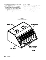
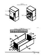
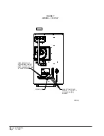
Remove air intake hood from return air area of unit.
(See Figure 1.)
2.
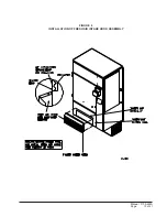
Install air intake hood. Refer to Item 17 of Basic
Installation (Field Installation).
3.
Refer to Control Wiring section for suggested
control schemes for the WFERV.
4.
After wiring, replace all panels.
CONTROL WIRING
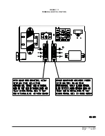
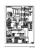
The WFERV comes from the factory with the low
voltage control wires wired into the wall mount low
voltage terminal strip (see wiring diagrams). Care must
be taken when deciding how to control the operation of
the ventilator. When designing the control circuit for
the ventilator, the following requirements must be met.
CONTROL REQUIREMENTS
1.
Indoor blower motor must be run whenever the
WFERV is run.
2.
Select the correct motor speed tap in the WFERV.
Using Table 1 of the WFERV Installation
Instructions, determine the motor speed needed to
get the desired amount of ventilation air needed.
For instance, do not use the high speed tap on a
WFERV if only 200 CFM of ventilation air is
needed. Use the low speed tap. Using the high
speed tap would serve no useful purpose and
significantly affect the overall efficiency of the
system. System operating cost would also increase.
3.
Run the WFERV only during periods when the
conditioned space is occupied. Running the
WFERV during unoccupied periods wastes energy,
decreases the expected life of the WFERV, and can
result in a large moisture buildup in the structure.
The WFERV removes 60 to 70% of the moisture in
the incoming air, not 100% of it. Running the
WFERV when the structure is unoccupied allows
moisture to build up in the structure because there is
little or no load. Use a control system that in some
way can control the system based on occupancy.
RECOMMENDED CONTROL SEQUENCES
Several possible control scenarios are listed below:
1.
Use a programmable electronic thermostat with
auxiliary terminal to control the WFERV based on
daily programmed occupance periods.
2.
Use a motion sensor in conjunction with a
mechanical thermostat to determine occupancy in the
structure. Bard markets the CS2000 for this use.
3.
Use a DDC control system to control the WFERV
based on a room occupancy schedule to control the
WFERV.
4.
Tie the operation of the WFERV into the light
switch. The lights in a room are usually on only
when occupied.
5.
Use a manual timer that the occupants turn to
energize the WFERV for a specific number of
hours.
6.
Use a programmable mechanical timer to energize
the WFERV and indoor blower during occupied
periods of the day.
VENTILATION AIRFLOW
The 240 volt WFERV is equipped with a 3-speed motor
to provide the capability of adjusting the ventilation
rates to the requirements of the specific application by
simply changing motor speeds.
* * IMPORTANT * *
Operating the WFERV during unoccupied
periods can result in a build up of moisture in
the structure.
Summary of Contents for WFERV-A-X
Page 10: ...Manual 2100 495A Page 10 of 21 FIGURE 5 INSTALLATION OF WFERV...
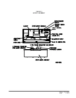
Page 11: ...Manual 2100 495A Page 11 of 21 FIGURE 6 WFERV ASSEMBLY...
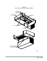
Page 13: ...Manual 2100 495A Page 13 of 21 FIGURE 8 INSTALLATION OF FRESH AIR INTAKE HOOD ASSEMBLY...
Page 18: ...Manual 2100 495A Page 18 of 21 FIGURE 10 THERMOSTAT WIRING DIAGRAM...
Page 19: ...Manual 2100 495A Page 19 of 21 FIGURE 11 TERMINAL BLOCK LOCATION...
Page 20: ...Manual 2100 495A Page 20 of 21 FIGURE 12 HUB ASSEMBLY WITH BALL BEARING...
Page 21: ...Manual 2100 495A Page 21 of 21...


