Manual 2100-495A
Page
5 of 21
BASIC INSTALLATION (Field Installation)
1.
Unpack the ventilator assembly, which includes the
integral ventilator with attached electrical harness
and miscellaneous hardware.
2.
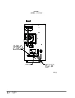
Remove intake hood assembly from back of
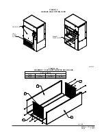
ventilator. (See Figure 1.)
3.
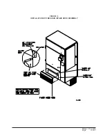
Remove the existing exterior vent option door on
the unit. (See Figure 2.)
4.
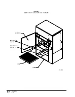
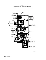
Remove and save existing unit air filter. Remove
and discard the rear exhaust cover plate. (See
Figure 3.)
5.
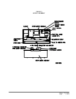
Install exhaust blower assembly in rear exhaust
opening and secure with four (4) screws. Position 4
pin connector so it is accessible. (See Figure 4.)
Assemble exhaust blower enclosure as shown in
Figure 2A. Fasten exhaust blower enclosure to
bottom of unit as shown in Figure 4.
6.
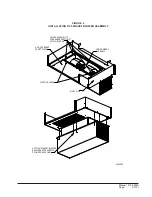
Install ventilator into the unit. (See Figure 5.)
IMPORTANT NOTE: Position front lip of ventilator
over front grille and on top of condenser partition.
(See Figure 5.) This is important to insure proper
l
e
d
o
M
h
t
i
W
e
s
U
r
o
F
s
t
i
n
U
g
n
i
w
o
l
l
o
F
l
a
c
i
r
t
c
e
l
E
V
R
E
F
W
5
2
1
-
0
5
0
F
W
1
-
8
0
2
/
0
3
2
e
s
a
h
p
3
r
o
drainage of any water entering damper assembly.
7.
Remove cassette and plug in exhaust blower.
Replace cassette. (See Figure 6.)
8.
Open control panel to gain access to unit low
voltage terminal block. (Insure all power is OFF
prior to opening the control panel.)
9.
Remove female plug of low voltage wiring harness
from the heat recovery assembly and snap into filter
rack. Route electrical harness leads through the 7/8"
bushing into the low voltage box. (See Figure 5.)
10. Connect leads C (black), W (blue), and G (orange)
with fork terminal to corresponding points on
terminal strip. (See Figure 7 for 230V units.)
NOTE: These 24 volt control wires control the
starting and stopping of the Energy Recovery
Ventilator and can be independently controlled
by an energy management control or timer.
See separate section on Control Wiring for
suggested control schemes.
11. Remove female plug of high voltage wiring harness
from the heat recover assembly and snap into filter
rack. Wire to terminal block. (See Figure 7 for
230V units.)
12. Plug male plug from female at filter rack.
(See Figure 5.)
13. Close control panel cover.
14. Replace filter and one (1) screw in condenser grille.
(See Figure 3)
15. Ventilator checkout
A. Resupply power to unit.
B. Energize the evaporator blower by
switching thermostat to the manual fan
position with Heat/Cool in OFF position.
C. Ventilator heat transfer wheels should
rotate slowly (49 RPM). Intake and
exhaust blowers should run.
(See Figure 9.)
D. De-energize the evaporator blower.
Energy Recovery wheels, and fresh air
and exhaust air blowers should stop.
E.
This completes ventilator checkout.
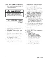
WARNING
Open breaker switch before installing this
accessory to prevent injury or death due to
electrical shock or contact with moving parts.
Turn thermostat to OFF.
Summary of Contents for WFERV-A-X
Page 10: ...Manual 2100 495A Page 10 of 21 FIGURE 5 INSTALLATION OF WFERV...
Page 11: ...Manual 2100 495A Page 11 of 21 FIGURE 6 WFERV ASSEMBLY...
Page 13: ...Manual 2100 495A Page 13 of 21 FIGURE 8 INSTALLATION OF FRESH AIR INTAKE HOOD ASSEMBLY...
Page 18: ...Manual 2100 495A Page 18 of 21 FIGURE 10 THERMOSTAT WIRING DIAGRAM...
Page 19: ...Manual 2100 495A Page 19 of 21 FIGURE 11 TERMINAL BLOCK LOCATION...
Page 20: ...Manual 2100 495A Page 20 of 21 FIGURE 12 HUB ASSEMBLY WITH BALL BEARING...
Page 21: ...Manual 2100 495A Page 21 of 21...


