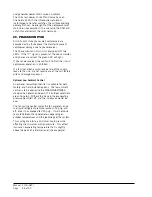
Manual 2100-587J
Page
39 of 59
33. INDOOR BLOWER OPERATION
The indoor blower motor is a constant CFM variable
speed direct drive motor. The motor is programmed
to respond to individual thermostatic inputs that
will determine the speed/airflow at which the motor
operates. The motor software maintains the rated
airflow across the range of allowable static whether the
system is ducted or free blow. It will also maintain the
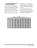
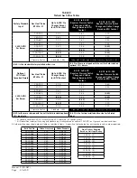
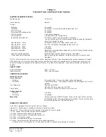
TABLE 9
Indoor Blower Performance
temperature rise across the gas heat exchanger at the
mid-point of the allowable rise range automatically.
There are not adjustments that can be made in the
field to adjust the airflows for any mode of operation.
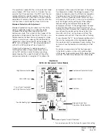
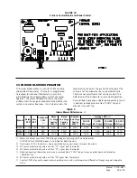
For duct-free applications where lower operating sound
is desired, remove pink wire from “COOL” tap and
move to “Unused” tap.
FIGURE 18
Furnace Control Board and Blower Control
Motor will deliver consistent CFM through voltage supply range with no deterioration
(197-253V for 230/208V models, 414-506V for 460V models).
Continuous CFM is the total air being circulated during continuous (manual) fan mode.
Will occur automatically with a call for “Y1” signal from thermostat.
Will occur automatically with a call for “Y2” signal from thermostat.
Reduced cooling airflow when pink wire is removed from “COOL” tap on furnace control board and placed on
“UNUSED” tap.
Will occur automatically with a call for “W” signal from thermostat.
Constant CFM of variable speed motor should maintain mid-rise temperature differential through range of allowable
static.
Model Rated
ESP
Max
ESP
Continuous
CFM
Rated
1st Stage
Cooling
CFM
Rated
2nd Stage
Cooling
CFM
Reduced
2nd Stage
Cooling
CFM
Heating CFM
50,000
BTU Input
75,000
BTU Input
100,000
BTU Input
125,000
BTU Input
WG3S2 0.15 0.50
800
800
1100
1000
1020
1250
1365
1410
WG4S2 0.20 0.50
825
1100
1500
1350
1020
1250
1365
1410
WG5S2 0.20 0.50
850
1300
1700
1500
1020
1250
1365
1410
Summary of Contents for WG Series
Page 11: ...Manual 2100 587J Page 11 of 59 FIGURE 2A Mounting Instructions for WG3S2...
Page 12: ...Manual 2100 587J Page 12 of 59 FIGURE 2B Mounting Instructions for WG4S2 and WG5S2...
Page 15: ...Manual 2100 587J Page 15 of 59 FIGURE 6 Common Wall Mounting Installations...
Page 25: ...Manual 2100 587J Page 25 of 59 FIGURE 11 Gas Pipe Connection...

