1 0 6
C H A N GE PARA METERS
6.9 CHANGE
P
A
R
AMETE
R
S / F
I
E
L
D CONT
R
O
L
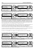
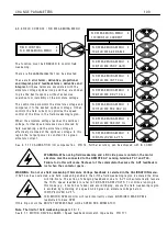
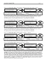
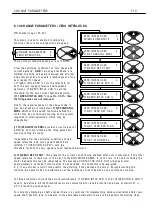
PIN number range 9 9-1 1 4
The f
i
e
l
d contro
ll
er w
i
th
i
n the PL/X cons
i
sts of a
s
i
ng
l
e phase ha
l
f contro
ll
ed thyr
i
stor br
i
dge w
i
th a
f
l
y w hee
l
d
i
ode. The A C supp
l
y to the br
i
dge
i
s
de
li
vered through term
i
na
l
s EL2 and EL3, and the
rect
i
f
i
ed output
i
s on term
i
na
l
s F + and F-. The
supp
l
y can be any w here
i
n the range of 1 0 0 to
4 8 0 V A C, but must, at
l
east, be 1.1 t
i
mes the
max
i
mum f
i
e
l
d output vo
l
tage you requ
i
re.
Note that the supp
l
y to EL2 and EL3
i
s a
l
so ut
ili
sed
to determ
i
ne phase rotat
i
on of the
l
oca
l
supp
l
y.
The purpose of the f
i
e
l
d w
i
nd
i
ng
i
n a motor
i
s to
prov
i
de f
l
ux that
i
ntersects the armature w
i
nd
i
ngs.
The f
l
ux generated
i
s a funct
i
on of the C URREN T
f
l
o w
i
ng
i
n the f
i
e
l
d co
il
s. W hen cons
i
der
i
ng the set
up of the f
i
e
l
d output you are ab
l
e to use 1 of 2
types of contro
l
strategy.
1) V o
l
tage c
l
amp w
i
th h
i
gher current
li
m
i
t
protect
i
on.
2) Current contro
l
w
i
th h
i
gher vo
l
tage c
l
amp
protect
i
on.
Motor f
i
e
l
d w
i
nd
i
ngs are norma
ll
y very
i
nduct
i
ve and
have a
l
ong t
i
me constant. Th
i
s resu
l
ts
i
n smooth
current
i
n the f
i
e
l
d. In th
i
s case the f
i
e
l
d current
read
i
ng
i
s reasonab
l
y accurate
i
rrespect
i
ve of w hen
i
t
i
s samp
l
ed.
Some motors have shorter f
i
e
l
d w
i
nd
i
ng t
i
me constants than norma
l
resu
l
t
i
ng
i
n up to 2 0 % r
i
pp
l
e. In th
i
s
case the PL/X may samp
l
e the current at a non-
i
dea
l
po
i
nt
i
n the cyc
l
e w h
i
ch w
ill
resu
l
t
i
n a s
li
ght
l
y
i
ncorrect
contro
l
l
eve
l
. (Usua
ll
y no more than a fe w %) To norma
li
se the f
i
e
l
d current back to
i
ts correct
l
eve
l
i
t may be
necessary to use the f
i
e
l
d current tr
i
m. See 6.1.1 2 C ALIBRA TIO N / F
m PIN 1 5, or
re-ca
li
brate the f
i
e
l
d current to overcome the
i
naccuracy.
W
a
r
n
i
ng.
F
i
e
l
d
r
e
v
e
r
s
a
l
o
r
d
i
s
c
onn
ec
t
i
on
.
Due to the h
i
gh
i
nductance of motor f
i
e
l
ds
i
t may take severa
l
seconds for the f
i
e
l
d current to decay to zero
after the f
i
e
l
d output has been
i
nh
i
b
i
ted by the PL/X.
Do not op
e
n
c
ir
c
u
i
t th
e
f
i
e
l
d un
l
e
ss th
e
f
i
e
l
d
c
u
rr
e
nt h
a
s
r
eac
h
e
d z
e
r
o
. The PL/X
i
s unab
l
e to measure the decay
i
ng current after an
i
nh
i
b
i
t, so
i
t
i
s not poss
i
b
l
e to use
the f
i
e
l
d current mon
i
tors or f
i
e
l
d act
i
ve f
l
ag to sho w zero current has actua
ll
y been atta
i
ned. It
i
s necessary
to observe the current on an externa
l
i
nstrument and t
i
me ho w
l
ong
i
t takes to decay. The
i
nterva
l
t
i
mer
b
l
ock may then be ut
ili
sed to
i
mp
l
ement a safety de
l
ay before open
i
ng the f
i
e
l
d c
i
rcu
i
t.
Fa
il
ure to observe th
i
s w arn
i
ng may cause f
l
ashover of the f
i
e
l
d c
i
rcu
i
t and resu
l
t
i
n damage to the system.
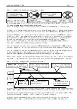
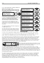
C H A N GE PAR A METERS 2
FIELD C O N TROL 3
R
FIELD C O N TROL 3
1 1 4)FIELD REFEREN CE
FIELD C O N TROL 3
9 9)FIELD EN A BLE
FIELD C O N TROL 3
FLD W E A KENIN G MENU 4
FIELD C O N TROL 3
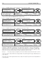
1 0 0)FIELD V OLTS OP %
FIELD C O N TROL 3
1 0 1)FIELD PROP G AIN
FIELD C O N TROL 3
1 0 2)FIELD IN T G AIN
FIELD C O N TROL 3
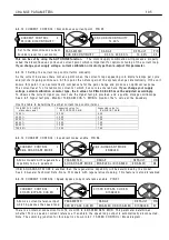
1 1 1)S T A NDBY FLD ENBL
R
R
FIELD C O N TROL 3
1 1 2)S T A NDBY FLD C UR
FIELD C O N TROL 3
1 1 3)FLD Q UEN C H DEL A Y
Summary of Contents for PLX
Page 2: ...2 Contents ...
Page 202: ......


