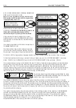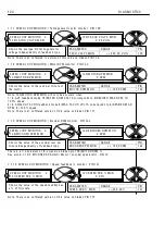
C H A N GE PARA METERS
1 0 9
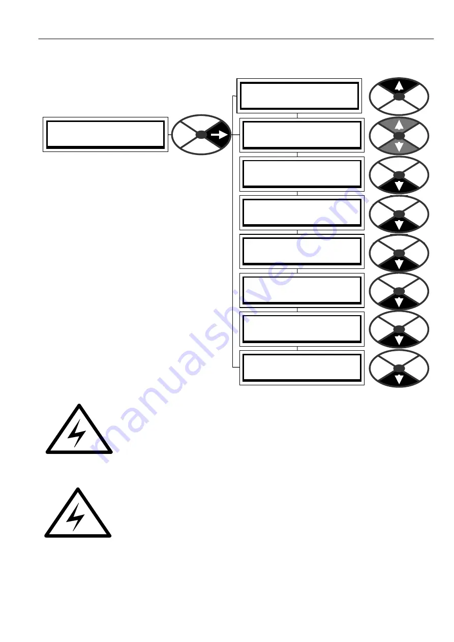
FIELD C O N TROL 3
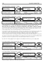
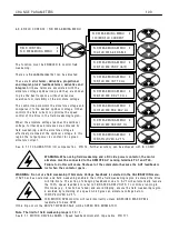
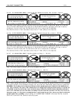
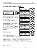
FLD W E A KENIN G MENU 4
FLD W E A KENIN G MENU 4
1 1 0)MIN FLD C URREN T
FLD W E A KENIN G MENU 4
1 0 3)FLD W E A K EN A BLE
FLD W E A KENIN G MENU 4
1 0 4)FLD W K PROP G AIN
FLD W E A KENIN G MENU 4
1 0 5)FLD W K IN T T C ms
FLD W E A KENIN G MENU 4
1 0 6)FLD W K DRV T C ms
FLD W E A KENIN G MENU 4
1 0 7)FLD W K FBK DRV ms
FLD W E A KENIN G MENU 4
1 0 8)FLD W K FBK IN T ms
FLD W E A KENIN G MENU 4
1 0 9)SPILLO V ER A V F %
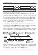
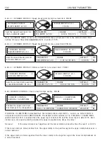
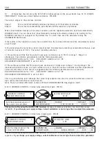
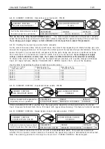
6.9.6 FIELD C O N TROL / FLD W E A KENIN G MENU
The funct
i
on must be EN A BLED to contro
l
f
i
e
l
d
w eaken
i
ng.
There are
5
c
ont
r
o
l
t
e
r
ms
that can be ad
j
usted.
These are
3
e
rr
o
r
t
e
r
ms, d
e
ri
v
a
t
i
v
e
, p
r
opo
r
t
i
on
a
l
a
nd
i
nt
e
g
r
a
l
, p
l
us 2 f
ee
db
ack
t
e
r
ms, d
e
ri
v
a
t
i
v
e
a
nd
i
nt
e
g
r
a
l
.
A
ll
these terms are assoc
i
ated w
i
th the
armature vo
l
tage sp
ill
over
l
oop and they are chosen
to g
i
ve the best response w
i
thout excess
i
ve
overshoots or
i
nstab
ili
ty of the armature vo
l
tage.
The contro
l
l
oop mon
i
tors the armature vo
l
tage and
compares
i
t to the des
i
red sp
ill
over vo
l
tage. It then
contro
l
s the f
i
e
l
d current to opt
i
m
i
se the speed
contro
l
of the dr
i
ve
i
n the f
i
e
l
d w eaken
i
ng reg
i
on.
W hen the armature vo
l
tage reaches the sp
ill
over
vo
l
tage, further speed
i
ncreases are ach
i
eved by
f
i
e
l
d w eaken
i
ng, and the armature vo
l
tage
i
s
effect
i
ve
l
y c
l
amped at the sp
ill
over vo
l
tage. In th
i
s
reg
i
on the output po w er
i
s constant for a g
i
ven
armature current.
See. 6.1.1 1 C ALIBR A TIO N / IR compensat
on PIN 1 4. Further accuracy can be ach
i
eved w
i
th IR C O MP.
WA
R
N
I
NG. Wh
e
n us
i
ng f
i
e
l
d w
eake
n
i
ng
a
nd
a
DC s
i
d
e
pow
e
r
c
ont
ac
to
r
, th
e
moto
r
a
r
m
a
tu
r
e
must b
e
c
onn
ec
t
e
d to th
e
R
EMOTE AV s
e
ns
i
ng t
e
r
m
i
n
a
l
s T41
a
nd T43.
F
a
il
u
r
e
to do th
i
s w
ill
ca
us
e
f
l
a
shov
e
r
of th
e
c
ommut
a
to
r
b
eca
us
e
th
e
AVF f
ee
db
ack
i
s
l
ost wh
e
n th
e
c
ont
ac
to
r
op
e
ns.
WA
R
N
I
NG. Do not us
e
f
i
e
l
d w
eake
n
i
ng
i
f A
r
m
a
tu
r
e
Vo
l
t
a
g
e
F
ee
db
ack
i
s s
e
l
ec
t
e
d
i
n th
e
CA
L
I
B
R
AT
I
ON m
e
nu.
If A V F has been se
l
ected, and f
i
e
l
d w eaken
i
ng enab
l
ed, then
i
f the f
i
e
l
d w eaken
i
ng reg
i
on
i
s entered the dr
i
ve
w
ill
tr
i
p. Note. The act
i
on of chang
i
ng feedback mode to A V F w
ill
automat
i
ca
ll
y resca
l
e
the 1 0 0 % speed feedback to refer to 1 8)RA TED A RM V OLTS. To cont
i
nue runn
i
ng
i
n
th
i
s mode (e.g.
i
f tacho has fa
il
ed) and avo
i
d tr
i
pp
i
ng, ensure the f
i
e
l
d w eaken
i
ng reg
i
on
i
s avo
i
ded by rema
i
n
i
ng at a speed w h
i
ch g
i
ves an armature vo
l
tage be
l
o w
1 0 9)SPILLO V ER A V F % .
1 3 0)M O T OR RPM mon
i
tor w
ill
read
i
ncorrect
l
y un
l
ess 6)DESIRED M A X RPM
i
s
read
j
usted to base RPM.
If th
i
s tr
i
p occurs the DRIV E TRIP MESS A GE w
ill
be SPEED FBK MISM A T C H.
Not
e
. Th
e
li
m
i
t of f
i
e
l
d w
eake
n
i
ng
r
a
ng
e
i
s 10 : 1.
Summary of Contents for PLX
Page 2: ...2 Contents ...
Page 202: ......


