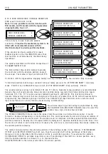
C H A N GE PARA METERS
1 1 3
6.10 CHANGE
P
A
R
AMETE
R
S / ZE
R
O
I
NTE
RL
OCKS
PIN number range 1 1 5-1 2 1.
Th
i
s menu
i
s used to enab
l
e 2
i
nter
l
ock
i
ng
funct
i
ons that are assoc
i
ated w
i
th zero speed.
There norma
l
standst
ill
behav
i
our
i
s as fo
ll
o w s.
A fter the sat
i
sfy
i
ng cond
i
t
i
ons of ‘zero speed and
current demand’,
AND
‘zero speed feedback’ are
fu
l
f
ill
ed, the f
i
r
i
ng pu
l
ses are removed and a
ll
other
l
oops rema
i
n act
i
ve to enab
l
e a rap
i
d response for a
ne w request for speed.
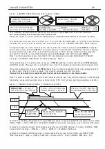
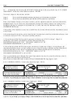
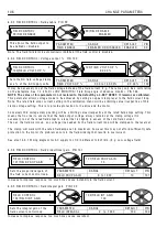
1 1 7)ZERO IN TLK SPD % sets the thresho
l
d for
both the zero speed reference and feedback
dec
i
s
i
ons. 1 1 8)ZERO IN TLK C UR % sets the
thresho
l
d for the zero current demand dec
i
s
i
on.
I
f 118
)
ZE
R
O
I
NT
L
K CU
R
%
i
s s
e
t to 0.00% th
e
n
th
e
f
iri
ng pu
l
s
e
s
a
r
e
not
r
e
mov
e
d.
Due to the rap
i
d response of the above mode,
i
t
may be necessary to
i
mp
l
ement
115
)
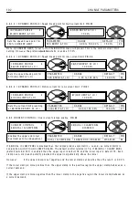
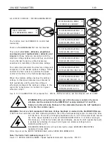
STANDST
I
LL
ENB
L
. W
i
thout th
i
s quench funct
i
on enab
l
ed the
motor may be cont
i
nuous
l
y mov
i
ng as the system
responds to sma
ll
var
i
at
i
ons, w h
i
ch may be
undes
i
rab
l
e.
i
)
115
)
STANDST
I
LL
ENB
L
prov
i
des an extra
l
eve
l
of
i
nh
i
b
i
t by not on
l
y remov
i
ng the f
i
r
i
ng pu
l
ses but
a
l
so quench
i
ng the
l
oops.
It operates after the sat
i
sfy
i
ng cond
i
t
i
ons of zero
speed reference, and zero speed feedback are
fu
l
f
ill
ed. 1 1 7)ZERO IN TLK SPD % sets the
thresho
l
d for both the zero speed ref and feedback dec
i
s
i
ons.
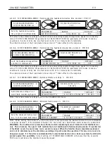
ii
)
116
)
ZE
R
O
R
EF STA
R
T
. Th
i
s prevents the current contro
l
be
i
ng enab
l
ed after a start command,
i
f the tota
l
speed reference to the dr
i
ve, or the
i
nput to the RUN M O DE RA MPS,
i
s not at zero. It
i
s used
i
f start
i
ng the
motor
i
nadvertent
l
y may be undes
i
rab
l
e. The message C O N T A C T OR LO C K O U T w
ill
appear after
approx
i
mate
l
y 2 seconds
i
f th
i
s funct
i
on
i
s not sat
i
sf
i
ed. The contactor
i
s de-energ
i
sed.
E. g. If an extruder
i
s fu
ll
of co
l
d p
l
ast
i
c, then start
i
ng
i
t may damage the scre w . By
i
mp
l
ement
i
ng th
i
s
funct
i
on the operator has to de
li
berate
l
y set the references to zero before he can commence runn
i
ng.
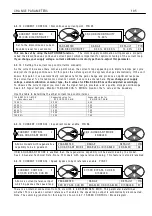
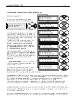
For these funct
i
ons to w ork the zero thresho
l
d
l
eve
l
s 1 1 7)ZERO IN TLK SPD % and 1 1 8)ZERO IN TLK C UR %
need to be def
i
ned. A
ll
the thresho
l
d
l
eve
l
s are symmetr
i
ca
l
for reverse rotat
i
on and have hyster
i
s
i
s of + /-
0.5 % around the chosen
l
eve
l
.
For systems emp
l
oy
i
ng a shaft encoder there
i
s a sub-menu for
i
mp
l
ement
i
ng sp
i
nd
l
e or
i
entat
i
on and/or zero
speed shaft pos
i
t
i
on
l
ock. In add
i
t
i
on to the ad
j
ustab
l
e parameters there are 4 d
i
agnost
i
c mon
i
tor
i
ng f
l
ags.
C H A N GE PAR A METERS 2
ZERO IN TERLO C KS 3
R
ZERO IN TERLO C KS 3
SPINDLE ORIEN T A TE 4
ZERO IN TERLO C KS 3
1 1 5)S T A NDSTILL ENBL
ZERO IN TERLO C KS 3
1 1 6)ZERO REF ST ART
ZERO IN TERLO C KS 3
1 1 7)ZERO IN TLK SPD %
ZERO IN TERLO C KS 3
1 1 8)ZERO IN TLK C UR %
ZERO IN TERLO C KS 3
1 1 9)A T ZERO REF FL A G
ZERO IN TERLO C KS 3
1 2 0)A T ZERO SPD FL A G
R
R
R
ZERO IN TERLO C KS 3
1 2 1)A T S T A NDSTILL
Summary of Contents for PLX
Page 2: ...2 Contents ...
Page 202: ......

