C O NFIG URA TIO N
1 6 9
13.2 Conf
i
gu
r
a
b
l
e
c
onn
ec
t
i
ons
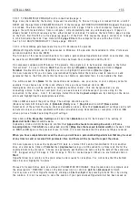
The
i
nterna
l
connect
i
ons w
i
th
i
n the PL/X may be re-conf
i
gured us
i
ng the d
i
sp
l
ay and keys, or PL PILO T.
Not
e
. To st
a
r
t
a
c
onn
ec
t
i
on
c
onf
i
gu
r
a
t
i
on s
e
ss
i
on ENAB
L
E GOTO, GETF
R
OM must b
e
s
e
t to ENAB
L
ED.
The PL/X possesses a versat
il
e range of pre-des
i
gned BLO C KS. S
i
gna
l
s need to be routed to the
i
nputs of
the b
l
ocks, processed
i
ns
i
de the b
l
ock, then routed from the output to the des
i
red dest
i
nat
i
on. Examp
l
es of
b
l
ocks are a s
i
gna
l
summer and a un
i
versa
l
term
i
na
l
i
nput. There are 2 types of connect
i
on too
l
w h
i
ch can be
programmed by the user ca
ll
ed G O T O and GET FRO M. It
i
s not poss
i
b
l
e to make
ill
ega
l
connect
i
ons
e. g. from output to output. It
i
s poss
i
b
l
e ho w ever to connect more than 1 G O T O to a
l
ega
l
p
i
n (eg an
i
nput)
and th
i
s w ou
l
d resu
l
t
i
n an error at the target PIN. The PL/X has a conf
li
ct checker w h
i
ch w arns of G O T O
connect
i
on conf
li
cts after conf
i
gurat
i
on. (W hen the user sets EN A BLE G O T O , GE T FRO M to DIS A BLED).
See 1 3.1 4 C O N FLIC T HELP MENU. See a
l
Not
e
. To
e
nd
a
c
onn
ec
t
i
on
c
onf
i
gu
r
a
t
i
on s
e
ss
i
on ENAB
L
E GOTO, GETF
R
OM must b
e
s
e
t to D
I
SAB
L
ED.
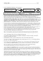
Note. It
i
s not poss
i
b
l
e to connect a G O T O d
i
rect
l
y to a GET FRO M. To do th
i
s f
i
rst connect the G O T O to a
ST A GIN G PO S T (or other unused PIN), then connect the GET FRO M to the same ST A GIN G PO ST.
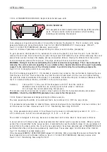
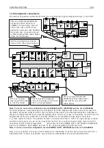
A OP1
GET FRO M
T 1 0
A OP1
PIN 2 5 2
O ffset
PIN 2 5 3
Rect/B
i
po
l
ar
PIN 2 5 1
PIN 1 5 9
OP mon
i
tor
Th
i
s
i
s a programmab
l
e GET
FRO M connect
i
on made from a
b
l
ock
i
nput to any other PIN
w
i
th
i
n b
l
ocks.
G O T O connect
i
on from a b
l
ock
output to any PIN except outputs
Th
i
s
i
s an externa
l
w
i
re connect
i
on made
to a PL/X term
i
na
l
.
Th
i
s connect
i
on
i
s made by
v
i
rtue of the des
i
gn of the b
l
ock
and
i
s not programmab
l
e.
PIN 4 0 5
PIN 4 1 3
PIN 4 1 3
PIN 4 0 3
PIN 4 1 3
PIN 4 1 3
PIN 4 0 8
Input 1
PIN 4 1 2
PIN 4 0 1
Output
P
i
n
6 9 2
No d
i
sp
l
ay
Subtota
l
output
No d
i
sp
l
ay
Subtota
l
output
P
i
n
6 9 1
PIN 4 1 0
Input 3
PIN 4 0 2
Input 2
Summer 1
PIN 4 1 3
PIN 4 1 3
PIN 4 0 7
Summer 1
G O T O
PIN 4 1 2
PIN
4 0 4
PIN
4 0 2
PIN
4 0 6
PIN
4 1 1
dead
band
Range
PIN 3 2 0
T 2
UIP2
Input
A N ALO G
G O T O
PIN 3 2 2
Sca
l
er
PIN 3 2 1
O ffset
PIN 3 2 5 / PIN 3 2 7
H
i
gh
Lo w
PIN 3 2 6 / PIN 3 2 8
G O T O OP1
H
i
gh va
l
ue 1
Lo w va
l
ue 1
H
i
gh va
l
ue 2
Lo w va
l
ue 2
G O T O OP2
PIN 1 6 2
D
i
g mon
Thresho
l
d
PIN
3 2 9
PIN 3 2 3
PIN 3 2 4
A na
l
og
mon
i
tor
PIN 1 5 0
Th
i
s
i
s a un
i
versa
l
programmab
l
e
connect
i
on dev
i
ce kno w n as a
JU MPER. It
i
s bas
i
ca
ll
y a p
i
ece of
v
i
rtua
l
w
i
re w
i
th a G O T O at the
dest
i
nat
i
on end and a GET FRO M at
the source end. It can
j
o
i
n any pa
i
r
of PINs
i
nc
l
ud
i
ng PINs w
i
th
i
n b
l
ocks
(There are 1 6
j
umpers).
Summary of Contents for PLX
Page 2: ...2 Contents ...
Page 202: ......

