4 2
Bas
i
c app
li
cat
i
on
4.5 CONT
R
O
L
ENG
I
NEE
R
I
NG COMM
I
SS
I
ON
I
NG
PR
OCEDU
R
ES
Before app
l
y
i
ng po w er to the L1/2/3 term
i
na
l
s for the f
i
rst t
i
me,
i
t
i
s recommended that a h
i
gh w attage
res
i
stor of bet w een 4 and 4 0 O hms
(
E.g.
a
1 Kw f
ir
e
b
a
r
)
i
s
i
nserted
i
n ser
i
es w
i
th the armature.
Th
i
s w
ill
li
m
i
t any potent
i
a
ll
y destruct
i
ve current and prevent poss
i
b
l
e thyr
i
stor damage.
(A typ
i
ca
l
examp
l
e of the cause of fau
l
t current
i
s the
i
ncorrect phas
i
ng of the EL/1/2/3 term
i
na
l
s w
i
th
respect to L1/2/3. W
i
thout the correct sem
i
-conductor fuses th
i
s may resu
l
t
i
n thyr
i
stor damage on the
app
li
cat
i
on of the start command).
(Note. The f
i
re bar w
ill
be removed pr
i
or to perform
i
ng the A U T O T UNE procedure as descr
i
bed
l
ater).
1) For systems us
i
ng f
i
e
l
d w eaken
i
ng, start w
i
th the un
i
t ca
li
brated for armature vo
l
tage feedback f
i
rst
i
n
order to ver
i
fy norma
l
operat
i
on up to base speed. Then
i
ntroduce f
i
e
l
d w eaken
i
ng on
l
y after carefu
l
ca
li
brat
i
on, and s w
i
tch
i
ng to e
i
ther tacho or encoder feedback.
2) For systems emp
l
oy
i
ng torque contro
l
i
t
i
s recommended to set up
i
n bas
i
c speed mode f
i
rst
i
n order to
estab
li
sh correct speed
l
oop funct
i
on
i
ng and ca
li
brat
i
on.
4.5.1 Q u
i
ck start ca
li
brat
i
on
Assum
i
ng that the dr
i
ve un
i
t
i
s correct
l
y
i
nsta
ll
ed and the motor and
l
oad are safe and ready to be rotated,
then the next task
i
s to ca
li
brate the dr
i
ve to su
i
t the supp
l
y and the motor.
The PL/X ser
i
es has a method of ca
li
brat
i
on w h
i
ch avo
i
ds the need to so
l
der res
i
stors and set s w
i
tches. A
ll
the fundamenta
l
dr
i
ve sca
li
ng parameters can be programmed v
i
a the on board d
i
sp
l
ay and menu keys.
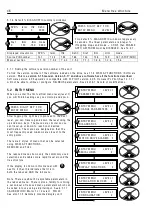
Once the
i
n
i
t
i
a
l
ca
li
brat
i
on menu
i
s comp
l
eted the chosen
li
m
i
ts may be saved and w
ill
rema
i
n una
l
tered
un
l
ess you w
i
sh to re-ca
li
brate. There
i
s a
l
so the cho
i
ce of us
i
ng a pass w ord to prevent unauthor
i
sed re-
ca
li
brat
i
on.
The un
i
t automat
i
ca
ll
y kno w s the mode
l
armature current rat
i
ngs and w
ill
prevent sett
i
ng of armature current
i
n excess of the mode
l
rat
i
ng.
See 1 3.1 3.4 DRIV E PERS O N ALIT Y / Armature current burden res
The parameters that w
ill
be se
l
ected for qu
i
ck start ca
li
brat
i
on are as fo
ll
o w s
See 6.1 C H A N GE P AR A METERS / C ALIBR A TIO N for a fu
ll
exp
l
anat
i
on of these parameters
Parameter
Range
Factory defau
l
t
Entered Un
i
ts
2)RA TED A RM A T URE A MPS
3 3 – 1 0 0 % of un
i
t rat
i
ng
3 3 %
A mps
3)C URREN T LIMIT %
0 – 1 5 0 % of un
i
t rat
i
ng
1 5 0 %
%
4)RA TED FIELD A MPS
0.1 A – 1 0 0 % of un
i
t rat
i
ng
2 5 %
A mps
5)B A SE RA TED RPM
0 - 6 0 0 0
1 5 0 0
Revs per m
i
nute of motor at
max
i
mum armature vo
l
ts
6)DESIRED M A X RPM
0 - 6 0 0 0
1 5 0 0
Max revs per m
i
nute of motor at
your des
i
red max speed
9)SPEED FEEDB A C K T YPE
Armature vo
l
tage (se
l
ect th
i
s one)
p
l
us 4 other cho
i
ces
Armature
vo
l
tage
Armature vo
l
tage
1 8)RA TED A RM V OLTS
0 – 1 0 0 0.0 V OLTS D C
4 6 0
V o
l
ts
1 9)EL1/2/3 RA TED A C
0 to 1 0 0 0.0
4 1 5 V
V o
l
ts A C
By se
l
ect
i
ng Armature V o
l
tage a qu
i
ck start
i
s more eas
il
y ach
i
eved.
1) The speed feedback
i
s a
l
w ays present, and
i
n the correct po
l
ar
i
ty.
2) The motor and/or
l
oad can be seen to be rotat
i
ng correct
l
y and at approx
i
mate
l
y the correct speed.
3) If a tachogenerator or encoder
i
s f
i
tted then
i
t can be checked for the correct po
l
ar
i
ty and output
l
eve
l
s
pr
i
or to
i
nc
l
ud
i
ng
i
t
i
n the feedback
l
oop.
4) O ther parameters such as ramp rates and stopp
i
ng modes can be checked and or set before
proceed
i
ng to f
i
na
l
accurate ca
li
brat
i
on.
5) The system may need pre-test pr
i
or to sh
i
pp
i
ng and no tachogenerator
i
s ava
il
ab
l
e. For th
i
s qu
i
ck start
procedure
i
t
i
s on
l
y necessary to set the above parameters.
Summary of Contents for PLX
Page 2: ...2 Contents ...
Page 202: ......


