Bas
i
c app
li
cat
i
on
4 3
4.5.2 Q u
i
ck start ca
li
brat
i
on step by step
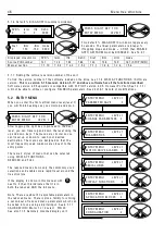
1) Turn on the contro
l
supp
l
y and press the r
i
ght
key to ex
i
t d
i
agnost
i
cs for the EN TRY MENU.
2) Press the r
i
ght key to enter the EN TRY MENU
/ C H A N GE P AR A METERS w
i
ndo w . Press the
r
i
ght key aga
i
n to enter the C H A N GE
PAR A ME TERS / RUN M O DE RA MPS menu. Then
press the up key for the CH A N GE P AR A METERS
/ C ALIBR A TIO N menu. Enter the C ALIBR A TIO N
menu by press
i
ng the r
i
ght key. Once there, use
the up or do w n key to trave
l
round the c
i
rcu
l
ar
menu.)
3) On
l
y 8 of the ava
il
ab
l
e parameters need to be
ad
j
usted for Q UIC K ST ART. (PINs 2, 3, 4, 5, 6,
9, 1 8, 1 9). Sk
i
p the other w
i
ndo w s.
4) Se
l
ect the qu
i
ck start parameters by us
i
ng the up / do w n keys. Press the r
i
ght key to enter the parameter
ad
j
ustment w
i
ndo w for each
i
n turn. Mod
i
fy each one to su
i
t your system us
i
ng the up/do w n keys. Use the
l
eft key to back out of each parameter ad
j
ustment w
i
ndo w and return to the c
i
rcu
l
ar C ALIBR A TIO N menu.
W hen you have f
i
n
i
shed mod
i
fy
i
ng the 8 qu
i
ck start parameters,
i
t
i
s t
i
me to save the changes you have
made. Use the
l
eft key to return to the EN TRY MENU / C H A N GE P AR A METERS menu. Use the up key to
arr
i
ve at EN TRY MEN U / P AR A METER S A V E. Use the r
i
ght key to enter the PAR A METER S A V E w
i
ndo w . Use
the up key to save the parameters. W h
il
e the save
i
s tak
i
ng p
l
ace the bottom
li
ne w
ill
read S A VIN G. W hen
the save
i
s comp
l
ete the bottom
li
ne w
ill
read FINISHED. You can no w return by ho
l
d
i
ng do w n the
l
eft key.
Th
i
s w
ill
take you to the defau
l
t d
i
agnost
i
cs, and then one tap r
i
ght to the EN TRY MENU.
Note. For a descr
i
pt
i
on of the defau
l
t d
i
agnost
i
cs see 5.1.6 Defau
No w the PL/X
i
s ca
li
brated to match your motor
i
t
i
s t
i
me to app
l
y 3 phase po w er for the f
i
rst t
i
me to
estab
li
sh correct funct
i
on
i
ng of the ma
i
n contactor and that the f
i
e
l
d current
i
s correct. Remember that there
shou
l
d be a f
i
re-bar
i
nserted
i
n the armature c
i
rcu
i
t to protect aga
i
nst fau
l
t currents.
See 4.2 Ma
on and 7.3 DIA G N O STIC S / FLD I LO OP M O NIT OR.
O nce you have estab
li
shed correct funct
i
on
i
ng of the ma
i
n contactor and that the armature and f
i
e
l
d are
rece
i
v
i
ng po w er as expected, then you must remove the f
i
re bar
i
n read
i
ness for the qu
i
ck start procedure.
4.5.3 Q u
i
ck start current
l
oop A U T O T U NE
5) The next step
i
s to set up the armature current
l
oop response. The un
i
t
i
s prov
i
ded w
i
th an autotune
fac
ili
ty that w
ill
perform th
i
s funct
i
on automat
i
ca
ll
y. Us
i
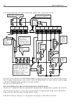
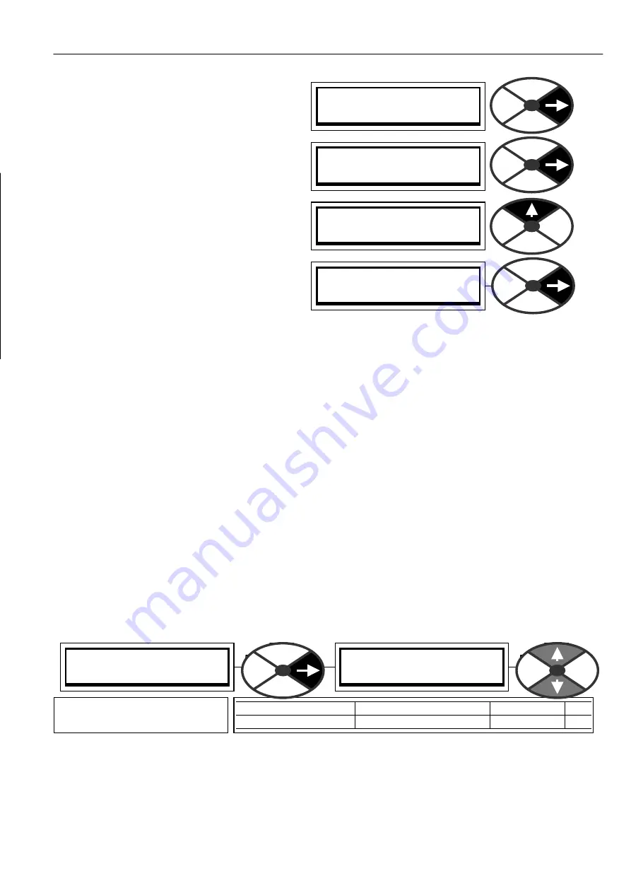
ng the keys go to C H A N GE PAR A METERS /
C URREN T C O N TROL, and then to C URREN T C O N TROL / A U T O T UNE EN A BLE.
Note. The autotune funct
i
on makes ad
j
ustments to the current
l
oop error amp
li
f
i
er PID terms to ach
i
eve
opt
i
mum performance. W hen EN A BLED
i
t w
ill
w a
i
t unt
il
the ma
i
n contactor
i
s energ
i
sed, and the dr
i
ve run,
before start
i
ng
i
ts autotune rout
i
ne. It may take from a fe w seconds up to about 1 m
i
nute typ
i
ca
ll
y. When
i
t
has f
i
n
i
shed
i
t drops out the ma
i
n contactor, sets the requ
i
red parameters and then automat
i
ca
ll
y DIS A BLES
i
tse
l
f. You can check that
i
t has f
i
n
i
shed by
l
ook
i
ng
i
n the d
i
sp
l
ay w
i
ndo w and w a
i
t
i
ng for the DIS A BLED
comment to re-appear on the bottom
li
ne. Th
i
s
i
s a stat
i
onary test. There
i
s no need to remove the
l
oad.
PRESS RIGH T KEY F OR
EN TRY MENU LE V EL 1
EN TRY MENU LE V EL 1
C H A N GE PAR A METERS 2
C H A N GE PAR A METERS 2
C ALIBRA TIO N 3
C H A N GE PAR A METERS 2
RUN M O DE R A MPS 3
C URREN T C O N TROL 3
9 2)A U T O T UNE EN A BLE
9 2)A U T O T UNE EN A BLE
DIS A BLED
PAR A ME TER
RA N GE
DEF A ULT
PIN
A U T O T UNE EN A BLE
EN A BLED OR DIS A BLED DIS A BLED
9 2
Enab
l
es the autotune funct
i
on
to start. It turns
i
tse
l
f off.
Summary of Contents for PLX
Page 2: ...2 Contents ...
Page 202: ......

