5 8
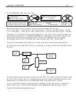
C H A N GE PARA METERS
C H A N GE PAR A METERS menu
There are a very
l
arge number of parameters that
can be a
l
tered by the user. A
ll
the a
l
terab
l
e
parameters have a factory defau
l
t sett
i
ng that
i
n
most cases w
ill
prov
i
de a perfect
l
y w orkab
l
e
so
l
ut
i
on and w
ill
not need a
l
ter
i
ng.
One c
l
ass of parameters that w
ill
need sett
i
ng
ho w ever
i
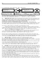
s the C ALIBR A TIO N va
l
ues. These are
spec
i
a
l
because they are used to set the max
i
mum
rat
i
ngs for the motor and dr
i
ve.
The abso
l
ute max
i
mum ava
il
ab
l
e armature current
of any part
i
cu
l
ar mode
l
w
ill
not norma
ll
y exceed the
C ALIBRA TIO N menu sett
i
ng. If the contro
l
card
i
s
transferred to a d
i
fferent po w er chass
i
s
i
t w
ill
automat
i
ca
ll
y
i
nterrogate the chass
i
s to determ
i
ne
the frame s
i
ze. The user must make sure that
i
f the
armature burden res
i
stor va
l
ue
i
s d
i
fferent, then the
ne w va
l
ue
i
s entered
i
nto the un
i
t. See 1 3.1 3.4
DRIV E PERS O N ALIT Y / Armature current burden
Th
i
s a
ll
o w s o w ners of
l
arge numbers of dr
i
ves to
ho
l
d m
i
n
i
ma
l
spares.
Somet
i
mes
i
t
i
s usefu
l
to return a un
i
t to
i
ts defau
l
t
parameter cond
i
t
i
on. E.g. a tr
i
a
l
conf
i
gurat
i
on may
prove to be un w orkab
l
e and
i
t
i
s eas
i
er to start
aga
i
n. If a
ll
4 keys are he
l
d do w n dur
i
ng the
app
li
cat
i
on of the contro
l
supp
l
y, then the dr
i
ve w
ill
automat
i
ca
ll
y refer to the defau
l
t parameters and
i
nterna
l
connect
i
ons.
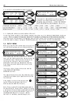
Ho w ever parameters that are used to match the motor to the dr
i
ve are not affected by restor
i
ng the defau
l
ts.
Th
i
s
i
nc
l
udes a
ll
thos
e
i
n th
e
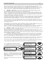
CA
L
I
B
R
AT
I
ON m
e
nu
a
nd 100
)
F
I
E
L
D VO
L
TS O
P
%,
(
fo
r
MOTO
R
1
a
nd MOTO
R
2
)
a
nd 680
)
I
a
r
m BU
R
DEN OHMS. Th
e
s
e
p
a
r
a
m
e
t
e
r
s
r
e
m
a
i
n
a
s p
r
e
v
i
ous
l
y
ca
li
b
r
a
t
e
d to p
r
e
v
e
nt
acc
i
d
e
nt
a
l
d
e
-
ca
li
b
r
a
t
i
on wh
e
n
r
e
sto
ri
ng d
e
f
a
u
l
ts
. See 5.1.3 Restor
See a
l
so 1 3.1 3.2 DRIV E PERS O N ALIT Y / Rec
pe page PIN 6 7 7, for deta
il
s of 2 and 3 key reset operat
i
on.
Th
i
s feature a
ll
o w s for 3 tota
l
i
nstrument rec
i
pes to be stored and retr
i
eved. W ARNIN G. Rec
i
pe page 2 and 3
each have the
i
r o w n set of ca
li
brat
i
on parameters, so be carefu
l
to check them a
ll
pr
i
or to runn
i
ng.
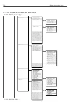
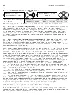
EN TRY MENU LE V EL 1
C H A N GE PAR A METERS 2
C H A N GE PAR A METERS 2
C ALIBRA TIO N 3
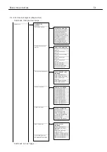
C H A N GE PAR A METERS 2
RUN M O DE R A MPS 3
C H A N GE PAR A METERS 2
J O G CRA WL SL A C K 3
C H A N GE PAR A METERS 2
M O T ORISED PO T RA MP 3
C H A N GE PAR A METERS 2
ST OP M O DE RA MPS 3
C H A N GE PAR A METERS 2
SPEED REF SU M MER 3
C H A N GE PAR A METERS 2
SPEED C O N TROL 3
C H A N GE PAR A METERS 2
C URREN T C O N TROL 3
C H A N GE PAR A METERS 2
FIELD C O N TROL 3
C H A N GE PAR A METERS 2
ZERO IN TERLO C KS 3
R
R
R
R
R
R
R
R
R
Summary of Contents for PLX
Page 2: ...2 Contents ...
Page 202: ......

