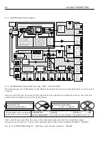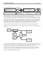
C H A N GE PARA METERS
6 1
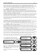
6.1.3 C ALIBRA TIO N / Current
li
m
i
t (%) PIN 3 Q UIC K S T ART
Th
i
s parameter may be ad
j
usted w h
il
st the PL/X
i
s runn
i
ng.
If a 1 5 0 % over
l
oad
li
m
i
t
i
s too
l
o w for your app
li
cat
i
on then
i
t
i
s poss
i
b
l
e to cater for
l
arger over
l
oad
percentages on motors sma
ll
er than the PL/X mode
l
armature current rat
i
ng.
See 6.8.3.1 C URREN T O V ERLO A D / O ver
If the current exceeds the
l
eve
l
set by the over
l
oad target, then after an appropr
i
ate d w e
ll
t
i
me,
i
t
i
s
progress
i
ve
l
y reduced to the over
l
oad target
l
eve
l
.
Tab
l
e sho w
i
ng max
i
mum over
l
oads accord
i
ng to:- Fu
ll
l
oad motor current, as a % of 2)RA TED ARM A MPS.
Fu
ll
l
oad motor current
(8 2)O/LO A D % T ARGE T) as
a % of 2)RA TED ARM A MPS
Max
i
mum ava
il
ab
l
e
Max
i
mum over
l
oad % ava
il
ab
l
e.
(W
i
th respect to fu
ll
l
oad motor current)
1 0 0 %
1 5 0 %
1 5 0 / 1 0 0 = 1 5 0 %
9 0 %
1 5 0 %
1 5 0 / 9 0 = 1 6 6 %
8 0 %
1 5 0 %
1 5 0 / 8 0 = 1 8 7 %
7 5 %
1 5 0 %
1 5 0 / 7 5 = 2 0 0 %
6 0 %
1 5 0 %
1 5 0 / 6 0 = 2 5 0 %
5 0 %
1 5 0 %
1 5 0 / 5 0 = 3 0 0 %
3 7.5 %
1 5 0 %
1 5 0 / 3 7.5 = 4 0 0 %
3 0 %
1 5 0 %
1 5 0 / 3 0 = 5 0 0 %
If 3)C URREN T LIMIT(%) or
i
f 8 2)O/LO A D % T ARGE T
l
eve
l
i
s set to 0 % then no permanent current w
ill
f
l
o w .
See 6.8.3.1 C URREN T O V ERLO A D / O ver
6.1.4 C ALIBRA TIO N / Rated f
i
e
l
d amps PIN 4 Q UIC K ST ART
If the f
i
e
l
d amps
i
s not g
i
ven on the motor datap
l
ate, you can deduce
i
t by measur
i
ng the res
i
stance of the
f
i
e
l
d w
i
nd
i
ng after a
ll
o w
i
ng
i
t to reach fu
ll
w ork
i
ng temperature, then us
i
ng the fo
ll
o w
i
ng equat
i
on
F
i
e
l
d current = F
i
e
l
d datap
l
ate vo
l
ts / Res
i
stance
i
n Ohms
A
l
ternat
i
ve
l
y
i
f you kno w the rated f
i
e
l
d vo
l
tage, you can go to the C H A N GE PAR A ME TERS / FIELD
C O N TROL menu, and se
l
ect the 1 0 0)FIELD V OLTS OP % c
l
amp parameter. A d
j
ust the f
i
e
l
d output vo
l
tage to
the datap
l
ate va
l
ue, as a % of the app
li
ed A C supp
l
y. P
l
ease ensure that 4)RA TED FIELD A MPS
i
s suff
i
c
i
ent
l
y
h
i
gh to force the 1 0 0)FIELD V OLTS OP % c
l
amp
i
nto operat
i
on at the des
i
red vo
l
tage under a
ll
cond
i
t
i
ons.
4)RA TED FIELD A MPS sca
l
ed by 1 1 4)FIELD REFEREN CE sets the demand for the f
i
e
l
d current contro
l
l
oop.
and 1 0 0)FIELD V OLTS OP % operates as a c
l
amp on the f
i
e
l
d br
i
dge f
i
r
i
ng ang
l
e.
The one that resu
l
ts
i
n the
l
o w er output, has pr
i
or
i
ty.
Hence
i
t
i
s poss
i
b
l
e to operate w
i
th the f
i
e
l
d current contro
l
preva
ili
ng and the vo
l
tage % as a h
i
gher safety
c
l
amp, or the vo
l
tage % c
l
amp preva
ili
ng and the f
i
e
l
d current contro
l
as a h
i
gher safety
l
eve
l
.
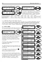
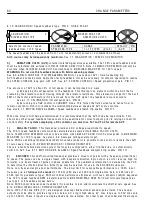
C ALIBRA TIO N 3
4)RA TED FIELD A MPS
4)RA TED FIELD A MPS
X X . X X A MPS
PAR A ME TER
RA N GE
DEF A ULT
PIN
RA TED FIELD A MPS
0.1 A -1 0 0 % of mode
l
rat
i
ng
2 5 % A MPS
4
Th
i
s
i
s the des
i
red 1 0 0 % D C
output f
i
e
l
d current
i
n amps
R
R
C ALIBRA TIO N 3
3)C URREN T LIMIT(%)
3)C URREN T LIMIT(%)
1 5 0.0 0 %
PAR A ME TER
RA N GE
DEF A ULT PIN
C URREN T LIMIT(%)
0 to1 5 0 % of rated motor amps 1 5 0. 0 0 % 3
Th
i
s
i
s the des
i
red current
li
m
i
t
% of 2)RA TED ARM A MPS
R
R
Summary of Contents for PLX
Page 2: ...2 Contents ...
Page 202: ......

