6 4
C H A N GE PARA METERS
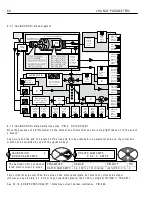
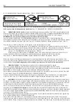
6.1.9 C ALIBRA TIO N / Speed feedback type PIN 9 Q UIC K S T ART
The speed feedback can be der
i
ved from 1 of 3 fundamenta
l
sources or a comb
i
nat
i
on of them.
A
ll
3 sou
r
ce
s m
a
y b
e
i
nd
e
p
e
nd
e
nt
l
y mon
i
to
r
e
d.
See 7.1 DIA G N O STIC S / SPEED LO OP M O NIT OR.
0
)
A
R
MATU
R
E VO
L
TS
(
AVF
)
.
Interna
l
i
so
l
ated s
i
gna
l
a
l
w ays ava
il
ab
l
e. The 1 0 0 % speed feedback vo
l
ts
must be ca
l
cu
l
ated and entered
i
nto PIN 1 8 RA TED ARM V OLTS. Note. 1 3 0)M O T OR RPM M O N w
ill
on
l
y be
accurate w hen 1 8)RA TED ARM V OLTS corresponds to 6)DESIRED M A X RPM, for 1 0 0 % speed.
WA
R
N
I
NG. Do not us
e
th
i
s f
ee
db
ack
mod
e
w
i
th f
i
e
l
d w
eake
n
i
ng syst
e
ms
.
See 6.9.6 FIELD C O N TROL / FLD W E A KENIN G MEN U for a note about A V F / f
i
e
l
d w eaken
i
ng tr
i
p.
A V F feedback conta
i
ns more r
i
pp
l
e than tacho feedback. It may be necessary for smooth operat
i
on to reduce
the SPEED C O N TROL
l
oop ga
i
n w
i
th A V F. See 6.7.4 SPEED C O N TROL / Speed proport
The accuracy of A V F
i
s about 2 % of fu
ll
speed,
i
t can be
i
mproved
i
n 2 w ays.
a) By app
l
y
i
ng IR compensat
i
on to the feedback. Th
i
s IR drop
i
s an e
l
ement w
i
th
i
n the A V F that
i
s
created by the armature current f
l
o w
i
ng through the armature res
i
stance. Th
i
s e
l
ement
i
s not part of the back
EM F of the motor and therefore
i
f
i
t
i
s removed from the A V F s
i
gna
l
, the feedback
i
s more accurate.
See 6.1.1 1 C ALIBR A TIO N / IR compensat
b) By runn
i
ng the f
i
e
l
d contro
l
i
n C URREN T mode. Th
i
s forces the f
i
e
l
d current (and hence f
l
ux) to
rema
i
n constant w h
i
ch
i
n turn makes the re
l
at
i
onsh
i
p bet w een speed and A V F more accurate.
See a
l
so 8.1.1 M O T OR DRIV E AL ARMS / Speed feedback m
W hen the dr
i
ve
i
s f
i
rst be
i
ng comm
i
ss
i
oned
i
t
i
s recommended that the A V F mode be used
i
n
i
t
i
a
ll
y. Th
i
s
a
ll
o w s any other speed feedback transducers to be exam
i
ned for correct outputs pr
i
or to re
l
y
i
ng on them for
contro
l
safety.
Fo
r
syst
e
ms
e
mp
l
oy
i
ng
a
DC
c
ont
ac
to
r
you must us
e
T41
a
nd T43 fo
r
r
e
mot
e
AVF.
1
)
ANA
L
OG TACHO
. Th
i
s transducer prov
i
des a D C vo
l
tage proport
i
ona
l
to speed.
The 1 0 0 % speed feedback vo
l
ts must be ca
l
cu
l
ated and entered
i
nto 8)M A X T A C H O V OLTS.
Note. 1 3 0)M O T OR RPM M O N w
ill
on
l
y be accurate w hen 8)M A X T A C H O V OLTS corresponds to 6)DESIRED
M A X RPM, for 1 0 0 % speed. See a
l
so 3.4.4 A na
Note. W
i
th an add
i
t
i
ona
l
b
i
-d
i
rect
i
ona
l
shaft mounted encoder
i
t
i
s poss
i
b
l
e to
l
ock and/or or
i
entate the shaft
at zero speed. See 6.1 0.9 ZERO IN TERLO C KS / SPINDLE ORIEN T A TE.
There
i
s a tacho fa
il
ure detect
i
on system that may be conf
i
gured to e
i
ther tr
i
p the dr
i
ve, or automat
i
ca
ll
y
s w
i
tch to A V F. See 8.1.1 M O T OR DRIV E AL ARMS / Speed feedback m
2
)
ENCODE
R
. Th
i
s shaft-mounted transducer prov
i
des a stream of pu
l
ses w
i
th a frequency proport
i
ona
l
to speed. The pu
l
ses can be a s
i
ng
l
e stream w
i
th a separate d
i
rect
i
on
l
og
i
c output. (Lo w for reverse, h
i
gh for
forw ard), or a dua
l
stream of pu
l
ses
i
n phase quadrature. The quadrature
i
nformat
i
on
i
s decoded by the PL/X
to determ
i
ne the rotat
i
on d
i
rect
i
on. E
i
ther type may be se
l
ected for use
i
n the EN C O DER sub menu.
Note. Lo w frequenc
i
es g
i
ve poor performance. The
l
o w er
li
m
i
t for reasonab
l
e performance
i
s a 1 0 0 %
i
nput
frequency (
i
e.
a
t fu
ll
sp
ee
d of
e
n
c
od
e
r
) of 1 5 Khz (4 5 0
li
nes at 2 0 0 0 rpm s
i
ng
l
e pu
l
se tra
i
n or 2 2 5
li
nes at
2 0 0 0 rpm for quadrature type). W
i
th more
li
nes performance
i
mproves, w
i
th
l
ess, dynam
i
c stab
ili
ty degrades.
The 1 0 0 % speed feedback RPM
i
s determ
i
ned from 6)DESIRED M A X RPM. For
l
o w er fu
ll
sca
l
e frequenc
i
es
see type 3 or 4 feedback modes be
l
o w .
Note. W
i
th b
i
-d
i
rect
i
ona
l
encoder feedback
i
t
i
s poss
i
b
l
e to
l
ock and/or or
i
entate the shaft at zero speed. See
6.1 0.9 ZERO IN TERLO C KS / SPINDLE ORIEN T A TE.
Note. DIP3 (T 1 6) and DIP4 (T 1 7) are des
i
gned to accept b
i
-d
i
rect
i
ona
l
encoder pu
l
se tra
i
ns. The encoder
outputs must be ab
l
e to prov
i
de a
l
og
i
c
l
o w be
l
o w 2 V , a
l
og
i
c h
i
gh above 4 V , may range up to 5 0 V max and
up to 1 0 0 KHz. These 2
i
nputs are s
i
ng
l
e ended and non-
i
so
l
ated. For other types of encoder e
l
ectr
i
ca
l
output,
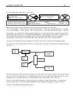
C ALIBRA TIO N 3
9)SPEED FBK T YPE
9)SPEED FBK T YPE
ARM A T URE V OLTS
PAR A ME TER
RA N GE
DEF A ULT PIN
SPEED FBK T YPE
1 of 5 T YPES (0 to 4)
(A V F)
9
Se
l
ects the source of speed
feedback from 1 of 5 types.
R
R
Summary of Contents for PLX
Page 2: ...2 Contents ...
Page 202: ......

