6 6
C H A N GE PARA METERS
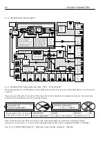
6.1.1 0. 1 EN C O DER S C ALIN G / Q uadrature enab
l
e PIN 1 0
The encoder
i
nputs on T 1 6 and T 1 7 can be programmed to accept 2 types of encoder pu
l
se tra
i
ns.
0
)
P
u
l
s
e
w
i
th s
i
gn. QUAD
R
ATU
R
E
(
D
I
SAB
L
ED
)
.
A s
i
ng
l
e tra
i
n of pu
l
ses on T 1 7 w
i
th a rotat
i
on d
i
rect
i
on
l
og
i
c s
i
gna
l
on T 1 6 (
l
o w for reverse, h
i
gh for forw ard). The
l
og
i
c
l
eve
l
may be
i
nverted us
i
ng the
1 3)EN C O DER SIG N parameter. Note. W hen th
i
s type of encoder
i
s used
i
n con
j
unct
i
on w
i
th A V F or tacho,
the feedback s
i
gn
i
s automat
i
ca
ll
y prov
i
ded by the ana
l
og feedback and T 1 6 d
i
g
i
ta
l
i
nput
i
s made free for
other uses. (Un
l
ess zero speed
l
ock
i
s requ
i
red. See 6.1 0.9 ZERO IN TERLO C KS / SPINDLE ORIEN T A TE. In
th
i
s case T 1 6
i
s st
ill
requ
i
red for the encoder d
i
rect
i
on.). See 6.1.9 C ALIBRA TIO N / Speed feedback type
1
)
2 pu
l
s
e
t
r
a
i
ns
i
n ph
a
s
e
qu
a
d
r
a
tu
r
e
. QUAD
R
ATU
R
E
(
ENAB
L
ED
)
.
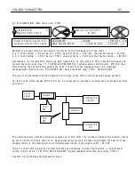
The encoder prov
i
des 2 pu
l
se tra
i
ns
phase sh
i
fted by 9 0 degrees. They are nom
i
nated the A tra
i
n (on T 1 7) and the B tra
i
n (on T 1 6). The A tra
i
n
shou
l
d
l
ead the B tra
i
n for forw ard rotat
i
on, (pos
i
t
i
ve demand) and B
l
eads A for reverse. The dr
i
ve
automat
i
ca
ll
y decodes the quadrature
i
nformat
i
on to produce a rotat
i
on d
i
rect
i
on s
i
gn. Th
i
s may be
i
nverted
us
i
ng the 1 3)EN C O DER SIG N parameter.
Note. W hen us
i
ng encoders w
i
th quadrature outputs
i
t
i
s very
i
mportant that the phase d
i
fference bet w een
the 2 pu
l
se tra
i
ns rema
i
ns as c
l
ose to 9 0 degrees as poss
i
b
l
e. If the encoder
i
s not mounted and centered
accurate
l
y on the shaft,
i
t can cause ske w
i
ng of the
i
nterna
l
opt
i
cs as the shaft rotates. Th
i
s produces a
severe degradat
i
on of the phase re
l
at
i
onsh
i
p on a cyc
li
ca
l
bas
i
s. If the encoder appears to gyrate as the shaft
rotates you must rect
i
fy the prob
l
em before try
i
ng to proceed w
i
th comm
i
ss
i
on
i
ng. The best w ay of check
i
ng
the output
i
s to use a h
i
gh qua
li
ty osc
ill
oscope and observe both pu
l
se tra
i
ns for good phase ho
l
d
i
ng and no
i
nterference. Do th
i
s w
i
th the dr
i
ve rotat
i
ng to + /- 10 0 % speed us
i
ng A V F as the feedback source.
Lo w frequency feedback may g
i
ve poor resu
l
ts at
l
o w speed. Hence for encoders or other types of
p
i
ck up prov
i
d
i
ng
l
ess than 1 5 KHz at fu
ll
speed
i
t
i
s recommended that mode 3 or mode 4 comb
i
ned
feedback type
i
s ut
ili
sed. See 6.1.9 C ALIBR A TIO N / Speed feedback type PIN 9 Q UIC K ST ART.
The encoder
i
nputs have to be ab
l
e to dea
l
w
i
th and recogn
i
se very short pu
l
ses. Th
i
s means that
i
t
i
s
not poss
i
b
l
e to prov
i
de heavy no
i
se f
il
ter
i
ng on these
i
nputs. Therefore
i
t
i
s very
i
mportant that the s
i
gna
l
s
i
nput on term
i
na
l
s 1 6 and 1 7 are c
l
ean and no
i
se free.
O ne of the pr
i
me causes of un w anted no
i
se on encoder s
i
gna
l
s
i
s ground
l
oops. If the encoder
e
l
ectron
i
cs
i
s earthed at the motor end then th
i
s may cause prob
l
ems.
Make sure the encoder e
l
ectron
i
cs 0 V
i
s separate
l
y w
i
red back to D 0 V on term
i
na
l
1 3, w
i
th no other
earth connect
i
ons at the motor end.
The encoder cas
i
ng w
ill
probab
l
y be earthed by v
i
rtue of
i
ts mechan
i
ca
l
connect
i
on to the motor or
mach
i
ne. Th
i
s
i
s usua
ll
y acceptab
l
e as
l
ong as the
i
nterna
l
e
l
ectron
i
cs 0 V has a separate connect
i
on. Some
encoder manufacturers prov
i
de a by-pass capac
i
tor
i
ns
i
de the encoder bet w een the e
l
ectron
i
cs 0 V and the
cas
i
ng. Unfortunate
l
y the capac
i
tor makes a very effect
i
ve h
i
gh frequency ground
l
oop and may have to be
removed to prevent ground
l
oop no
i
se on the encoder s
i
gna
l
s. (Consu
l
t encoder supp
li
er).
U
l
t
i
mate
l
y
i
t may be necessary to
i
nsta
ll
an
i
so
l
at
i
on
li
nk
i
n the encoder
l
oop.
Make sure the encoder cab
l
es are routed a w ay from heavy current or other no
i
se generat
i
ng cab
l
es. Use
i
nsu
l
ated screened cab
l
e w
i
th a separate screen for each encoder s
i
gna
l
connected at the dr
i
ve term
i
na
l
T 1 3.
The encoder 0 V and + 2 4 V shou
l
d a
l
so be screened w
i
th
i
n the cab
l
e.
EN C O DER S C ALIN G 4
1 0)Q U A DRA T URE EN A BLE
1 0)Q U A DRA T URE EN A BLE
EN A BLED
PAR A ME TER
RA N GE
DEF A ULT
PIN
Q U A DR A T URE EN A BLE
EN A BLED / DIS A BLED
EN A BLED
1 0
Programmes the encoder
i
nputs
T 1 6 and T 1 7.
R
R
Summary of Contents for PLX
Page 2: ...2 Contents ...
Page 202: ......


