background image


Example: 

  5 channel MEME™ Voice control layout.  

Cabinet vibrations are a significant source of distortion and coloration in most loudspeakers.  The primary 
mechanism that generates cabinet vibrations is simple Newtonian action and reaction.  As the driver motor 

(magnet and voice coil) forces the cone to move back and forth in 
order to generate sound, the cone exerts an equal and opposite 
force on the motor.  This force is transmitted through the driver 
frame to the cabinet, vibrating the cabinet walls and coloring the 
sound emitted by the cone.  This effect is most especially prevalent 
in the low frequency drivers where the cone motion is greatest.    

While, the MicroMain26 is built with a massive and well braced 
cabinet, we also tackle the problem at its source by eliminating 
vibrations before they even begin.   This is achieved through our 
innovative force cancellation design.  The low frequency drivers are 
mounted on opposing sides of the cabinet and their motors are 
locked together.  As the cones are driven in and out in opposite 
directions the forces exerted on the motors cancel one another.  
The vibrations never make it to the cabinet because they are not 
allowed to develop in the first place.   

This layout has further benefits.  Since the drivers are locked 
together, the motors and frames function as a massive internal 
metal cabinet bracing.   And because the wavelengths generated by 
the subwoofers are much larger than the speaker cabinet 
dimensions, the subs radiate as if they were a single point source 
located on axis with the tweeter. 

MEME™ Voice Selector Connection: 

The MEME™ Voice Selector switch box is 
connected to the Voice jack of the speaker via any 
standard 3.5 mm stereo phone cable.  The included 
6-way splitter can be used to control the Voice 
Emulation of up to 5 speakers.  Furthermore, the 
input impedance of the Voice jack is very high.  So, 
additional splitters can be daisy chained in order to 
control virtually any number of speakers with the 
MEME™ Voice Selector switch.

Caveat:  Plugging the speaker into different mains 
outlets can potentially cause erratic behavior in the 
MEME™ control.  The safety grounds of different 
outlets can sometimes have ground potential 
differences of a few volts of more.  The resulting 
voltage spread between the grounded chassis of 
various speakers can cause the MEME™ control 
inputs to read incorrect settings or become 
unstable.  Care must be taken with the studio 
mains power and safety ground layout.  If this is a 
concern, please consult a qualified electrician. 

Force Cancellation 

Summary of Contents for MicroMain26

Page 1: ...Owner s Manual...

Page 2: ...you refer to this information in twhe event of an insurance claim such as loss or theft CLICK HERE TO REGISTER NOW PRODUCT REGISTRATION PROTECT YOUR BAREFOOT MONITORS Please complete the product regis...

Page 3: ...5 25 woofers feature a phalanx of advanced technology yielding upper bass and lower midrange detail that rivals any driver on the planet Barefoot s innovative Multi Emphasis Monitor Emulation technol...

Page 4: ...ungrounded mains power cable or a mains connection that is ungrounded This may result in personal injury Do not place open flames such as lighted candles on or near this device Do not expose this devi...

Page 5: ...carries both left and right audio signals For stereo or multiple speaker operation the monitor output signal must be assigned to two or more AES3 output XLRs within the DAW Otherwise a passive AES sp...

Page 6: ...For digital signals also set the Channel toggle switch to left L or right R in accordance with the speaker position 3 Ensure that the audio signal is fully attenuated AES3 signal requires digital atte...

Page 7: ...s Subwoofers Amplifi DACs 24bit 192k Hz Limiters Sub Level Crossovers and MEME Input Level ADC 24bit 192kHz Receiver 24bit 192kHz ANLG AES3 INPUT CHNL LEVEL VOICE SUB Clip LED 6 0 Signal Flow Diagram...

Page 8: ...have zero effect on the audio signal below their thresholds The front LED indicator light will flash RED when a RMS Limiter on any of the driver channels is triggered Caution Signals large enough to...

Page 9: ...ears crossing a few inches behind the head A typical placement scenario might have the speakers positioned 2 feet 60cm from the front wall the tweeters at ear level and the speakers and listening posi...

Page 10: ...desirable to stand the MM26 in the vertical orientation This will result in sacrifice to the width of the sweet spot Place the speakers as mirror images with both tweeters either to the outside or th...

Page 11: ...istening positons This can be achieved by aiming the speaker axes more forward such that the axes cross further behind the center listening position The figure below illustrates the general principle...

Page 12: ...eaker to overheat and shut down 9 0 Pedestal Attachment Caution The pedestals should never be used to lift or sus pend the MM26 Each MM26 is supplied with two pedestal legs The pedes tals provide clea...

Page 13: ...water Disconnect the mains power cable when cleaning to avoid risk of electric shock Do not use alcohol based cleaners Driver active surfaces such as diaphragms and surrounds may be cleaned using dry...

Page 14: ...outstanding translation Setting has a flat frequency response and extremely fast transient response This is the default voice when the Voice Selector Switch is not connected Hi Fi While it does not e...

Page 15: ...ed to develop in the first place This layout has further benefits Since the drivers are locked together the motors and frames function as a massive internal metal cabinet bracing And because the wavel...

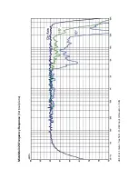
Page 16: ...MicroMain26 Frequency Response Horizontal plane dB SPL at 1 meter free field 15 dBV input attenuator 0db...

Page 17: ...MicroMain26 Frequency Response Vertical plane dB SPL at 1 meter free field 15 dBV input attenuator 0db...

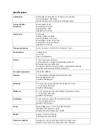
Page 18: ...frames function as lateral cabinet bracing Long fiber wool acoustic damping throughout Crossover Frequencies 100 800 4000 Hz Tweeter 1 ring radiator with Advanced neodymium motor Rear waveguide chambe...

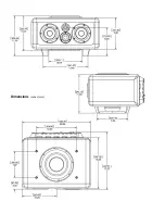
Page 19: ...Dimensions inches mm...

Page 20: ...nability to use the product Under no circumstances shall BAREFOOT SOUND be liable for any loss cost expense inconve nience or damage exceeding the purchase price of the product The warranty and remedi...

Page 21: ...UND will repair or replace your product at BAREFOOT SOUND s discretion and will ship it back to you within 2 weeks dependent on parts availability via FedEx 4 Cross exchange Parts only You will need t...

Page 22: ...rvice the product BAREFOOT SOUND will not warrant any problems repair tickets or on our website BAREFOOT SOUND makes every effort to make sure all information on our website is correct LIMITED WARRANT...

Page 23: ...Barefoot Sound LLC barefootsound com...

Reviews: