Bareknuckle Welterweight - Airless Paint Sprayer
OPERATING INSTRUCTIONS & SAFETY MANUAL
Bareknuckle Welterweight - Airless Paint Sprayer
OPERATING INSTRUCTIONS & SAFETY MANUAL
|
20 |
21
28
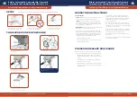
Micro Computer Controlled
Board
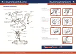
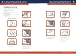
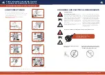
Sealing ring replace:
1.
Removed the rear cover with 5” allen wrench.
2.
Loosen two screws on pump frame with 5” allen wrench, the pump to be removed from the pump frame.
3.
Loosen four screws which connector the pump and pump cover with 4” allen wrench.
4.
Open the pump cover, take out the connecting rod component and the gear.
5.
Screw out the connector with special sleeve.
6.
Carefully check the piston rod and seal and o-ring and other parts for wear and scratches, if any, should be replaced immediately,
(
head the ball into the connector seat, can remove piston, sealing ring, etc.
)
7.
With special sleeve screw the connector to pump body and tighten in place.
8.
Put the connector assembly and gear into pump hosing.
9.
Locking pump cover and pump housing with screw, then pump loaded on the frame, and cover the rear cover.
10.
Assembled the Suction tube and Priming tube component.
11.
According to operating Instructions
steps to
activate and check the equipment without dripping.
Note:
1. All components apply a little oil before assembled.
2.
Even if a sealing ring is damaged, must be replaced the whole repair parts.
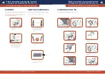
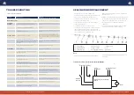
230V Airless Sprayer Electrical Installation Drawing
Electricity (230V)
Heat Pressure Control
Protection Switch
Electrical
Switch
Motor
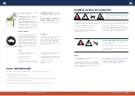
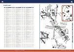
a. Joint stopper b. O-ring 22.5*1.8 c. Stopper sleeve
d. Position washer e. Copper washer f. Felt
g. Connector seat h. Copper guide bushing i. Connector
Problem
What To Check
(If check is OK, go to next check)
What To Do
(When check is not OK, refer to this column)
Motor Won’t Operate
Basic Fluid
Pressure
1. Pressure control knob setting. Motor will not run
if set at minimum (fully counter-clockwise).
1. Slowly increase pressure setting to see if motor
starts.
2. Spray tip or fluid filter may be clogged.
2. Relieve pressure, then clear clog or clean gun
filter.
3. Machines does not pump.
3. Depress reset button beneath the pump to loosen
the ball.
Basic Mechanical
1. Pump frozen or hardened paint.
1. Thaw sprayer if water or water-based paint has
frozen in sprayer. Place sprayer in warm area to
thaw. Do not start sprayer until thawed completely.
If paint hardened (dried) in sprayer, replace pump
packings.
2. Displacement pump connecting rod pin.
Pin must be completely pushed into connecting rod
and retaining spring must be firmly in groove or
pump pin.
2. Push pin into place and secure with spring
retainer.
3. Motor. Remove drive housing assembly.
3. Replace motor if fan won’t turn.
Low Output
1. Worn spray tip.
1.Relieve pressure, replace tip.
2. Verify pump does not continue to stroke when
gun trigger is released.
2. Service pump.
3. Prime valve leaking.
3. Relieve pressure, then repair prime valve.
4. Suction tube connections.
4. Tighten any loose connections. Check o-ring on
suction tube.
5. Electric supply with volt meter.
Meter must read 220-240 Vac or 110V(According to
models). Low voltages reduce sprayer performance.
5. Reset building circuit breaker; replace building
fuse. Repair electrical outlet or try another outlet.
6. Extension cord size and length.
6. Replace with a correct, grounded extension cord.
7. Leads from motor to circuit board for damaged or
loose wire connectors. Inspect wiring insulation and
terminals for signs of overheating.
7. Be sure male terminal pins are centered and
firmly connected to female terminals. Replace
any loose terminals or damaged wiring. Securely
reconnect terminals.
8. Worn motor brushes which must be
greater than 1/4 in. (6 mm).
8. Replace brushes.
9. Motor brushes binding in brush holders.
9. Clean brush holders. Remove carbon dust by
using compressed air to blow out brush dust.
10. Low stall pressure. Turn pressure control knob
fully clockwise.
10. Replace pressure control assembly.
11. Motor armature for shorts by using an armature
tester (growler) or perform spin test.
11. Replace motor.
TROUBLESHOOTING
SEALING RING REPLACEMENT
230V AIRLESS SPRAYER ELECTRICAL INSTALLATION DRAWING
1. Common Problems of Equipment
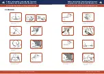
1. Removed the rear cover with 5” Allen wrench.
2. Loosen two screws on pump frame with 5” Allen wrench,
the pump to be removed from the pump frame.
3. Loosen four screws which connector the pump and
pump cover with 4” Allen wrench.
4. Open the pump cover, take out the connecting rod
component and the gear.
5. Screw out the connector with special sleeve.
6. Carefully check the piston rod and seal and o-ring and
other parts for wear and scratches, if any, should be
replaced immediately, (head the ball into the connector
seat, can remove piston, sealing ring, etc.)
7. With special sleeve screw the connector to pump body
and tighten in place.
8. Put the connector assembly and gear into pump hosing.
9. Locking pump cover and pump housing with screw, then
pump loaded on the frame, and cover the rear cover.
10. Assembled the Suction tube and Priming tube
component.
11. According to operating Instructions steps to activate
and check the equipment without dripping.
NOTE:
1. Apply a little oil to all components before assembly.
2. Even if a sealing ring is damaged you must replace all
worn parts.


