background image

Page 5

A

A

Functionality may vary depending on the distance from the corner.

Optional 

– Corner installation

Max. TV Size

80

”\203cm

3

Page 7

FULL TIGHTENING

NO FORCE

Connect the TV Plate with the Adaptors to the TV in all 4 connection holes.

Position the Adaptors according to your TV

’s hole pattern.

600mm

400mm

200

mm

300

mm

Max. 600mm

Ma

x

400

mm

300mm

300

mm

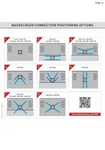
Z1/Z2/Z3

Z6

Z4/Z5

Z7

Optional

For more positioning options turn to page 12.

Summary of Contents for BM464L

Page 1: ...e maximum weight indicated Using heavier products might cause injury If you are satisfied with the product please give us a 5 stars rating on the website you bought it from If you are not satisfied pl...

Page 2: ...tet representerar ditt tagande att noggrant l sa och f lja instruktionerna N r produkten installeras p offentliga platser b r de ansvariga p dessa platser se till att den anv nds enligt instruktionern...

Page 3: ...talaci zodpov dnost Nedodr en bezpe nostn ch a mont n ch pokyn m e zp sobit p d a n sledn po kozen Va eho elektronick ho p stroje Po rozbalen si pozorn p e t te mont n n vod a ve vlastn m z jmu jej do...

Page 4: ...olat r tege al f rni HU Kotwica musi by zanu ona powy ej 10 mm 3 8 w gipsowej warstwie PL Kotvu je t eba zapustit zapu t na nejm n 10 mm 3 8 do vrstvy omitky CZ Kotvu je treba zapusti zapusten najmene...

Page 5: ...nem alkalmas falra s mennyezetre val felszerel sre amelyek a k vetkez anyagokb l k sz ltek gipsz t bl b l sz raz falb l enyh n kidolgozott t mb kb l szilik t t bl kb l t gl kb l sz raz gyenge vagy nag...

Page 6: ...r Cable Management Wall Plate Plastic Cover Included Parts not to scale Y7 x2 x4 x1 x1 x8 A B C E Z6 W1 W2 W3 x8 x8 x8 Y1 Y3 Y6 x2 x1 x2 Y4 x1 x1 D S1 x6 x1 x4 Z7 x2 Y2 Y5 x1 pcs L inch L mm M 4 3 4 2...

Page 7: ...to the back of the TV Continue according to your TV mounting hole pattern Wrong Right Use the spacers Z7 in order to adjust the screws length inside the TV Purchase longer screws 75x75 mm up to 200X20...

Page 8: ...bove 200x200 mm up to 600x400 mm Curved screen P1 1 Flat screen 2 PARTIAL TIGHTENING Disassemble the screws connect the 4 adaptors to the TV plate and reassemble the screws C D D C P1 Right Wrong Righ...

Page 9: ...Size 80 203cm 3 Page 7 FULL TIGHTENING NO FORCE Connect the TV Plate with the Adaptors to the TV in all 4 connection holes Position the Adaptors according to your TV s hole pattern 600mm 400mm 200mm 3...

Page 10: ...ing holes center and the bottom of the TV in order to set the required height of the TV Install the bracket on the Wall Make sure the distance between the 2 holes is correct 5 9 14 9 cm 8 20 3 cm E 11...

Page 11: ...e steps according to your wall type Mark the holes on the wall according to the required height Use a Stud Finder 4b Page 8 4a Page 8 Make sure all holes are drilled inside the studs CONNECTION POINTS...

Page 12: ...e plaster coating 4b 5 32 4mm 2 75 70mm 2 75 70mm 1 4 6mm 1 3 8 10mm 2 75 70mm 2 3 8 10 mm W2 FULL TIGHTENING Drill with 5 32 4mm drill bit First use 1 4 6mm drill bit Afterwards use 3 8 10mm drill bi...

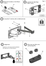
Page 13: ...ont Arms B to the Bracket A Paste the 6 stickers on the Plastic Covers Apply force on the upper part of the Bracket and make sure it is well connected FULL TIGHTENING B A S1 S1 6 Assemble the Wall Pla...

Page 14: ...perly on 2 small beams Front Arms 10 11 Assemble the nut housing P2 make sure that the tab is inserted into the slot Make sure that the tab is inserted into the slot P2 upside down T part P3 Assemble...

Page 15: ...FALL PROOF 14 Place the TV cables in the Cable Management 15 Level the TV Z2 Z3 Insert and tighten the screws from both sides to create friction for the tilt mechanism Adjust the TV tilt angle carefu...

Page 16: ...Page 12...
Reviews: