10
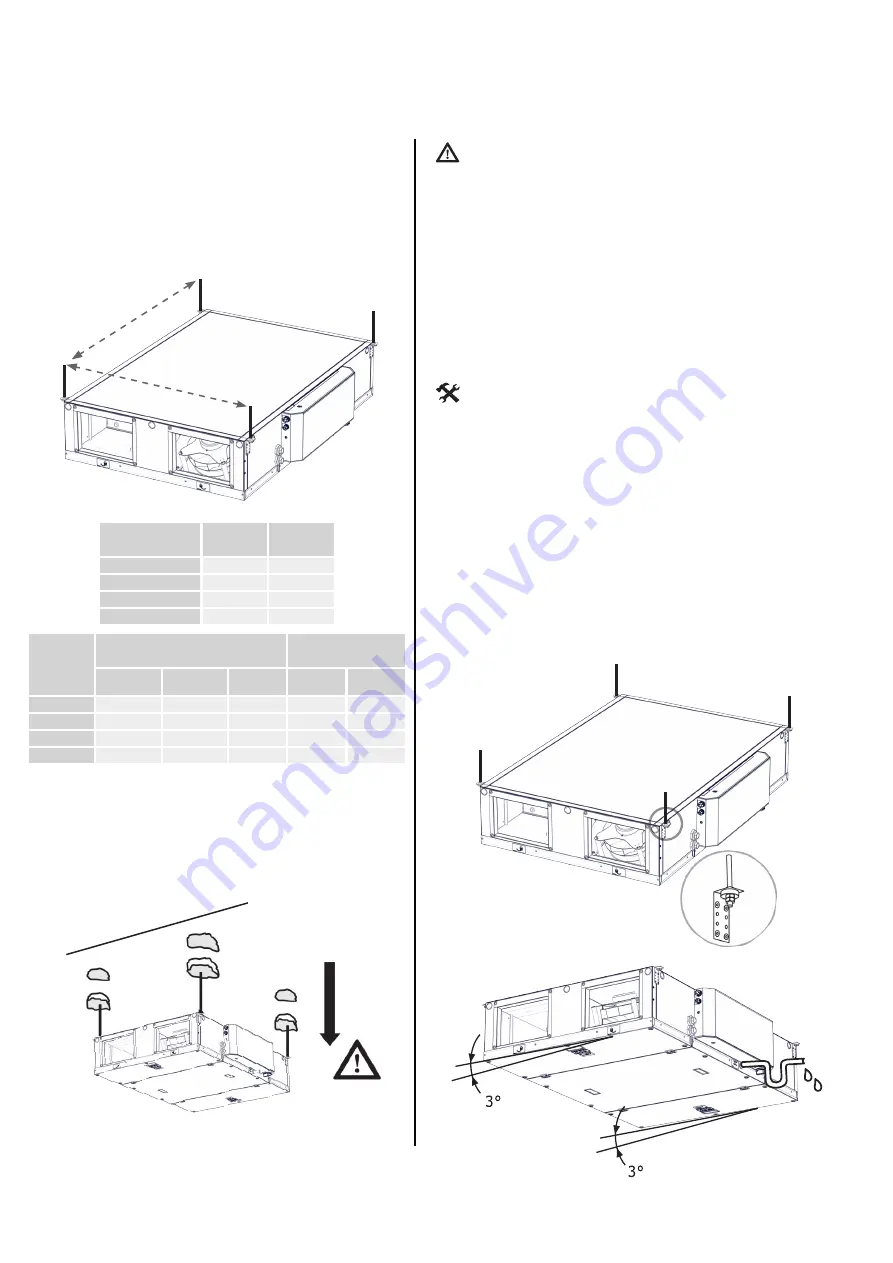
6.1-3 Hanging the unit
For location of the anchorage points, use the drill-
ing template listed below.
The units are equipped with mounting brackets
which should be used in conjunction with threaded
drop rods ZTZ-M8/1.0 or equivalent to facilitate
levering and leveling.
•
Due to the weight of the unit, it is necessary to
use an appropriate lifting device when assem
-
bling (e. g. a forklift, scissor lift, etc...)
•
It’s recommended that the unit is installed into
position before making connections to duct
and pipe work or electrical connections.
•
Depending on the type of building structure
there can be a number of ways of attaching
the suspension system, such as drilled-in fix
-
ings, clamps and clips, wedge nuts, etc.. En
-
sure whatever system is utilized it has suffi
-
cient strength to support the unit.
•
4-6 M8 check nuts (according to the unit type)
•
4-6 stud bolts
•
4-6 dowels of a suitable type and dimension
(according to the ceiling material and the unit
weight)
•
Driller with drills of a suitable type and dimen
-
sion
•
Tongs and nut wrenches
Place the unit horizontally and then incline it by 3°
by adjusting the nuts on the drop rods so that the
condensate drains into the outlet connection on
the access side of the unit.
ATTENTION!
YOU WILL NEED
6. INSTALLATION
Establish the weight of each unit and make sure
that ceiling will be adequate to support up to four
times the weight of the unit.
Drill the holes in the ceiling, try the strength of its
material and attach the unit by the side brackets
using the hanging rods ZTZ-M8/1.0 or equivalent.
A
B
Type
A
B
HRFL2-040
700
1120
HRFL2-070
1000
1330
HRFL2-150
1300
1630
HRFL2-200
1630
1930
Type
Weight of unit (kg)
Weight of accesso-
ries (kg)
Without
reheating
With electric
reheating
With water
reheating
WCO
mod-
ule
DX module
HRFL2-040
70
75
75
25.5
24
HRFL2-070
90
95
95
32
30
HRFL2-150
165
170
170
37
35
HRFL2-200
240
245
245
43
40


