background image

B1: DIXELL OPERATING INSTRUCTIONS

dIXEL

Operating instructions

1592002701

1592002701 XH240L-V  GB r1.0 12.01.2004 *


XH240L - XH240V

1/4

XH240L – XH240V

TEMPERATURE AND HUMIDITY CONTROLLER

1.


GENERAL WARNING

1.1


PLEASE READ BEFORE USING THIS MANUAL

x


This  manual  is  part  of  the  product  and  should  be  kept  near  the  instrument  for  easy  and
quick reference.

x


The instrument shall not be used for purposes different from those described hereunder. It
cannot be used as a safety device.

x


Check the application limits before proceeding.

1.2


 SAFETY PRECAUTIONS

x


Check the supply voltage is correct before connecting the instrument.

x


Do  not  expose  to  water  or  moisture:  use  the  controller  only  within  the  operating  limits
avoiding sudden temperature changes with high atmospheric humidity to prevent  formation
of condensation

x


Warning: disconnect all electrical connections before any kind of maintenance.

x


Fit  the  probe  where  it  is  not  accessible  by  the  End  User.  The  instrument  must  not  be
opened.

x


In case of failure or faulty operation send the instrument back to the distributor or to “Dixell
s.r.l.” (see address) with a detailed description of the fault.

x


Consider the maximum current which can be applied to each relay (see Technical Data).

x


Ensure that the wires for probes, loads and the power supply are separated and far enough
from each other, without crossing or intertwining.

x


In case of applications in industrial environments, the use of mains filters (our mod. FT1) in
parallel with inductive loads could be useful.

2.


GENERAL DESCRIPTION

The 

XH240L,


38x185 

format, and the 

XH240V,


100x64 

format, are microprocessor controllers,

suitable for applications on medium temperature refrigerating units. They control both humidity
and temperature. They have  4 output relays to control compressor, heating elements , fan and
humidifier. They have 2 analogue inputs: one for temperature control, the other one for humidity.
There is one digital input (free contact) configurable by parameter. An  output allows the user to
programme the parameter list with the 

“Hot Key”.

3.


TEMPERATURE REGULATION

The temperature regulation is performed through neutral zone using compressor and heater
output relays.

Set point

OFF

ON

• 

Heating

 output: CUT IN is “SET_TEMP-dbt”, CUT OUT is when the temperature reaches the

set point.
• 

Compressor

  output  CUT  IN  is  “  SET_TEMP  +dbt”,  CUT  OUT  is  when  the  temperature

reaches the set point.

3.1


DEFROST

Defrost  is  performed  through  a  simple  stop  of  the  compressor.  Parameter  “

IdF

”  controls  the

interval between defrost cycles, while its length is controlled by parameter “

MdF

”.

To 

disable 

the defrost set the 

MdF

 parameter to 

zero

Humidity regulation during a defrost depends on the 

Hud 

parameter.

With  

Hud=no

 humidity regulation is disabled.

Con 

Hud=yES

 humidity regulation is performed also during a defrost.

4.


HUMIDITY REGULATION

The  humidity  regulation  is  performed  through  neutral  zone,  by  humidifying  dehumidifying
actions.
Humidity  control  can  be  disabled  setting  the  SET_RH  to  “nu”  value.  In  this  case  only  the
temperature control is perform.

4.1


HUMIDIFYING ACTION

The humidifying action is done enabling the humidifier relay when the humidity is lower than the
“SET_RH-dbH” value.
The relay is switch off when humidity reaches the set values.

4.2


DEHUMIDIFYING ACTION

The  dehumidifying  action  is  performed  enabling  the  heating  and  compressor  outputs  together
when humidity is higher than dbH value.
Outputs are disabled when humidity comes back to the SET_RH value.

4.2.1  Relation between cooling, heating and dehumidifying

1.


If  is  simultaneously  present  a  request  of  cooling  (temp>Sdbt)  and
dehumidifying  (RH  >  dbH):  the  cooling  action  has  the  priority  over  the
dehumidifying  action:  only  the  compressor  relay  is  energised  till  the  SET_TEMP  is
reached at this point also the heating relay is enabled.

2.


If  is  simultaneously  present  a  request  of  heating  (temp<  SET_TEMP-dbt)  and
dehumidifying  (RH  >  dbH):  the  dehumidifying  action  has  the  priority  over  the
heating action: both the compressor and the heating relays are energised till the humidity
set is reached at this point only the heating relay is enabled.

5.


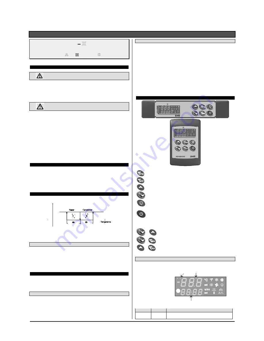
THE DISPLAY

To display and modify target temperature set point. (SET_TEMP)

To display and modify target humidity set point (SET_RH); in programming mode it
selects a parameter or confirm an operation.
In  programming  mode  it  browses  the  parameter  codes  or  increases  the  displayed
value.

In  programming  mode  it  browses  the  parameter  codes  or  decreases  the  displayed
value. By holding it pressed for 3s the defrost is started

Switch ON and OFF the light, if present

Switch ON and OFF the instrument.

KEY COMBINATIONS


+


To lock and unlock the keyboard


+

To enter the programming mode.


+


To exit the programming mode.

5.1


ICONS AND SYMBOLS

Each LED function is described in the following table.

LED2

LED3

LED4

Temperature Display 

Humidity Display 

LED

MODE

FUNCTION

Led 4

ON

- Instrument in stand by.
- In “Pr2” indicates that the parameter is also present in “Pr1”.

Summary of Contents for AGB

Page 1: ...ase Cleaning 14 15 Parts Ordering 16 Appendices Table of Contents To ensure proper functionality and optimum performance it is STRONGLY recommended that Hillphoenix specialty cases be installed servic...

Page 2: ...ii...

Page 3: ...ith shelf lighting systems for direct or indirect exposure to water or other liquids The use of a misting system or water hose on a display case with a shelf lighting system resulting in the direct or...

Page 4: ...installation and operations handbooks accompanied by an alert symbol paired with the word DANGER WARNING or CAUTION All warning messages will inform you of the potential hazard how to reduce the risk...

Page 5: ...parts list_09 12 energy data and parts list_01 13 endviews_03 13 text update and air ow diagram_06 13 energy data_07 13 energy data_02 14 endviews and energy data_09 14 support diagram and parts page...

Page 6: ...Watts Amps Watts Amps Watts Amps Watts AGB 4 6 8 Model Lights per Row Light Length ft Fluorescent Lighting Per Light Row Clearvoyant LED Lighting Per Light Row Standard Power Cornice or Shelf High Pow...

Page 7: ...ghted shelves Add the following for lighted shelves 4 Fluorescent 80 BTUH 3 Fluorescent 60 BTUH 4 Shelf LED 36 BTUH 4 Canopy LED 72 BTUH 3 Shelf LED 27 BTUH 3 Hi Output LED 54 BTUH 6 EPR valve is fact...

Page 8: ...cm 21 13 16 in 55 4 cm 49 13 16 in 126 5 cm 93 1 2 in 237 5 cm 93 1 2 in 237 5 cm 49 1 4 in 125 1 cm 49 1 4 in 125 1 cm REFLECTIVE REAR LOAD DOORS REFLECTIVE REAR LOAD DOORS 30 PROFILE 36 PROFILE 48...

Page 9: ...e it is delivered to the consumer Our liability ceases at the time of shipment RECEIVING CASES Examine fixtures carefully and in the event of shipping dam age and or shortages please contact the Servi...

Page 10: ...cross support and lower the horizontal support on to the shim packs Repeat on the other end of the case LOCATION This refrigerated display case has been designed for displaying and storing perishable...

Page 11: ...umper for nal t and n ish Be certain to use an appropriate cutting tool tubing or PVC cutter to ensure a smooth cut 7 Install case shelves and reconnect lights Be aware that differing shelf con gurati...

Page 12: ...ns are compliant with local codes C A U T I O N Be sure to remove all styrafoam shipping blocks from piping and refrigerant lines Failure to do so may result in case damage Fig 4 P trap drain outlet P...

Page 13: ...43 8 cm 8 case 18 in 45 7 cm 14 in 35 6 cm 28 in 71 1 cm 30 34 in 86 4 cm 36 30 in 76 2 cm 36 in 91 4 cm 26 in 66 0 cm 30 32 in 81 3 cm 36 TOEKICK 15 x 15 MECHANICAL ACCESS FOR ELECT REFRIG AND DRAIN...

Page 14: ...G E R SHOCK HAZARD Always disconnect power to case when cleaning servicing or con guring components of the light ing system Failure to do so may result in serious injury or death REPLACING T 8 LIGHTS...

Page 15: ...remove Re installing shelf luminaires 1 Place hook into shelf roll form at shelf front and rotate rear of luminaire toward the shelf 2 Depress the rear clip so that luminaire can nish rotation and un...

Page 16: ...ines see pg 8 After powering up the case be certain that all of the steps listed below have been completed to ensure proper case functionality safety and compliance with warranty terms 1 Check all lig...

Page 17: ...a case 1 Store Conditions Hillphoenix cases are designed to oper ate in an air conditioned store that maintains a 75 F 24 C store temperature and 55 max relative humidity ASHRAE conditions Case opera...

Page 18: ...he luminaires down with a soft damp cloth Avoid using harsh or abrasive cleaners as they may dam age the lights Be certain that the luminaires are complete ly dry before re energizing Clean from top t...

Page 19: ...product only extra strength or specialty products may not be suitable Glass Plus standard product only extra strength or specialty products may not be suitable Exceed Multi Surface Glass Cleaner from...

Page 20: ...case for which the part is intended Length of the part if applicable Color of part if painted or color of polymer part Whether part is for left or right hand application Quantity Data tag is located o...

Page 21: ...A1 A2 Wiring Information B1 B4 Dixell Operating Instructions C1 Sporlan Pressure Temperature Chart D1 Parts List APPENDIX 17...

Page 22: ...A1 WIRING DIAGRAM...

Page 23: ...UE LIGHT BLACK LIGHT SWITCH WHITE FROM 2 2 BLACK BALLAST WHITE BALLAST BLACK LIGHT RED LIGHT BLACK FROM BLOCK 1 1 BLACK TO DIXELL 5 41 WHITE TO DIXELL 6 42 WHITE SOL JUNCTION BOX 26 27 78 BLACK TO CHI...

Page 24: ...int 3 1 DEFROST Defrost is performed through a simple stop of the compressor Parameter IdF controls the interval between defrost cycles while its length is controlled by parameter MdF To disable the d...

Page 25: ...ow and above the humidity set point SET_RH The dehumidifying action is enabled when the humidity increases and reaches the SET_RH dbH value It is stopped when it comes back to the SET_RH The humidifyi...

Page 26: ...ring this time and then for the delay dot and doH after closing the door the temperature and humidity alarms are disabled 7 2 GENERIC ALARM I1F EAL As soon as the digital input is activated the unit w...

Page 27: ...ative humidity 20y85 no condensing Measuring and regulation range NTC probe 40 110 C 58 230 F Resolution 0 1 C or 1 C or 1 F selectable Accuracy ambient temp 25 C 0 5 C 1 digit 13 WIRING CONNECTIONS 1...

Page 28: ...29 4 381 8 17 8 3 16 4 51 5 54 3 30 4 388 0 18 7 8 17 0 52 7 55 6 31 4 394 3 19 7 2 17 7 54 0 56 9 32 4 400 7 20 6 7 18 4 55 3 58 3 33 5 407 2 21 6 1 19 1 56 6 59 6 34 6 413 8 22 5 6 19 9 58 0 61 0 3...

Page 29: ...S Wire Riser F Front Toekick G Outside Front H End Toekick I Dry or Refrigerated Lower Storage J End Panel K Fixed End Glass L Shelf Standard M Outside Back N Rear Load Doors O Light Guard P Upper Int...

Page 30: ...rned within two weeks after startup 5 If the defective part is not returned to the Manufacturer 6 To service maintenance or wear and tear parts such as lights starters and ballasts MODIFICATIONS TO GE...

Page 31: ...er directly on fan motors or any electrical connections All lighting receptacles must be dried off prior to insertion and re energizing the lighting circuit Please refer to the Use and Maintenance sec...

Reviews: