background image

B1: DIXELL OPERATING INSTRUCTIONS

dIXEL


Installing and Operating Instructions 

1592020070


1592020070 XR70CX GB m&M r1.130.11.2007.doc 

XR70CX 

1/4 

Digital controller with defrost and fans management


XR70CX 


1.


GENERAL WARNING 

1.1


PLEASE READ BEFORE USING THIS MANUAL 

x


This manual is part of the product and should be kept near the instrument for easy and quick reference. 

x


The instrument shall not be used for purposes different from those described hereunder. It cannot be 
used as a safety device. 

x


Check the application limits before proceeding. 

1.2


 SAFETY PRECAUTIONS 

x


Check the supply voltage is correct before connecting the instrument. 

x


Do not expose to water or moisture: use the controller only within the operating limits avoiding sudden 
temperature changes with high atmospheric humidity to prevent  formation of condensation 

x


Warning: disconnect all electrical connections before any kind of maintenance. 

x


Fit the probe where it is not accessible by the End User. The instrument must not be opened. 

x


In case of failure or faulty operation send the instrument back to the distributor or to “Dixell S.p.A.” (see 
address) with a detailed description of the fault. 

x


Consider the maximum current which can be applied to each relay (see Technical Data). 

x


Ensure that the wires for probes, loads and the power supply are separated and far enough from each 
other, without crossing or intertwining. 

x


In case of applications in industrial environments, the use of mains filters (our mod. FT1) in parallel with 
inductive loads could be useful. 

2.


GENERAL DESCRIPTION 

Model 

XR70CX

, format 32 x 74 mm, is microprocessor based controller, suitable for applications on 

medium  or  low  temperature  ventilated  refrigerating  units.  It  has  four  relay  outputs  to  control 
compressor, fan, and defrost, which can be either electrical or reverse cycle (hot gas). The last one 
can be used as light, for alarm signalling or as auxiliary output. It is also provided with up to four NTC 
or  PTC  probe  inputs,  the  first  one  for  temperature  control,  the  second  one,  to  be  located  onto  the 
evaporator, to control the defrost termination temperature and to managed the fan. The digital input 
can  operate  as  third  temperature  probe.    The  fourth  one,  to  connect  to  the  HOT  KEY  terminals  is 
used to signal the condenser temperature alarm or to display a temperature.. 
The HOT KEY output allows to connect the unit, by means of the external module XJ485-CX,  to a 
network  line 

ModBUS-RTU

  compatible  such  as  the 

dIXEL 

monitoring  units    of  X-WEB family. It 

allows to program the controller by means the HOT KEY programming  keyboard.  
The  instrument  is  fully  configurable  through  special  parameters  that  can  be  easily  programmed 
through the keyboard. 

3.


CONTROLLING LOADS 

3.1


COMPRESSOR 

The  regulation  is  performed  according 
to  the  temperature  measured  by  the 
thermostat  probe  with  a  positive 
differential  from  the  set  point:  if  the 
temperature  increases  and  reaches  set 
point  plus  differential  the  compressor is 
started  and  then  turned  off  when  the 
temperature reaches the set point value 
again. 

Time

Temper.

Compr.

SET

ON


In  case  of  fault  in  the  thermostat  probe  the  start  and  stop  of  the  compressor  are  timed  through 
parameters “

COn

” and “

COF

”. 

3.2


DEFROST 

Two defrost modes are available through the “

tdF

” parameter: defrost through electrical heater (

tdF 

=  EL

)  and  hot  gas    defrost  (

tdF  =  in

).  Other  parameters  are  used  to  control  the  interval  between 

defrost  cycles  (IdF),  its  maximum  length  (MdF)  and  two  defrost  modes:  timed  or  controlled  by  the 
evaporator’s probe (P2P).  
At the end of defrost dripping time is started, its length is set in the FSt parameter. With FSt =0 the 
dripping time is disabled. 

3.3


CONTROL OF EVAPORATOR FANS 

The fan control mode is selected by means of the “

FnC

” parameter: 

FnC = C_n:

  fans will switch ON and OFF with the compressor and

 not run

 during defrost; 

FnC = o_n

  fans will run even if the compressor is off, and not run during defrost; 

After defrost, there is a timed fan delay allowing for drip time, set by means of the “

Fnd

” parameter. 

FnC = C_Y

   fans will switch ON and OFF with the compressor and 

run

 during defrost; 

FnC = o_Y

  fans will run continuously also during defrost 


An additional parameter “

FSt

” provides the setting of temperature, detected by the evaporator probe, 

above  which  the  fans  are  always  OFF.  This  is  used  to  make  sure  circulation  of  air  only  if  his 
temperature is lower than set in “FSt”. 

3.3.1  Forced activation of fans 

This  function  managed  by  the 

Fct

  parameter  is  designed  to  avoid  short  cycles  of  fans,  that  could 

happen  when  the  controller  is  switched  on  or  after  a  defrost,  when  the  room  air  warms  the 
evaporator. 

Functioning: 

if  the  difference  of  temperature  between  the  evaporator  and  the  room 

probes is more than the value of the Fct parameter, the fans are switched on. With Fct=0 the function 
is disabled. 

3.3.2  Cyclical activation of the fans with compressor off. 

When  Fnc  =  c-n  or  c-Y  (fans  in  parallel  to  the  compressor),  by  means  of  the  Fon  and  FoF 
parameters the fans can carry out on and off cycles even if the compressor is switched off. When the 
compressor is stopped the fans go on working for the Fon time. With Fon =0 the fans remain always 
off, when the compressor is off.  

4.


FRONT PANEL COMMANDS 


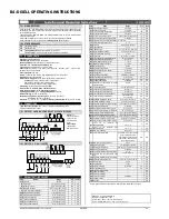
: To display target set point; in programming mode it  selects a parameter  or confirm an 

operation. 

 (DEF) 

To start a manual defrost 


  (

UP)

:  To  see  the  max.  stored  temperature;  in  programming  mode  it  browses  the  parameter 

codes or increases the displayed value. 

 (

DOWN

) To see the min stored temperature; in programming mode it browses the parameter 

codes or decreases the displayed value. 


To switch the instrument off, if onF = oFF.  


To switch the light, if oA3 = Lig. 

KEY COMBINATIONS: 


To lock & unlock the keyboard

.


+


To enter in programming mode. 


+


To return to the room temperature display. 

4.1


USE OF LEDS 

Each LED function is described in the following table. 

LED 

MODE 

FUNCTION 


ON 

Compressor enabled 


Flashing  Anti-short cycle delay enabled 


ON 

Defrost enabled 


Flashing  Drip time in progress 


ON 

Fans enabled 


Flashing  Fans delay after defrost in progress. 


ON 

An alarm is occurring 


ON 

Continuous cycle is running 

  ON 

Energy saving enabled 


ON 

Light on 

ON 

Auxiliary relay on 

°C/°F 

ON 

Measurement unit 

°C/°F 

Flashing  Programming phase 

5.


MAX & MIN TEMPERATURE MEMORIZATION 

5.1


HOW TO SEE THE MIN TEMPERATURE 

1. 


Press and release the 

n

 key. 

2. 


The “Lo” message will be displayed followed by the minimum temperature recorded. 

3. 


By pressing the 

n

 key again or by waiting 5s the normal display will be restored. 

5.2


HOW TO SEE THE MAX TEMPERATURE 

1. 


Press and release the 

o

 key. 

2. 


The “Hi” message will be displayed followed by the maximum  temperature recorded. 

3. 


By pressing the 

o

 key again or by waiting 5s the normal display will be restored. 

5.3


HOW TO RESET THE MAX AND MIN TEMPERATURE RECORDED 

1.


Hold press the SET key for more than 3s, while the max. or min temperature is displayed. (rSt 
message will be displayed) 

2.


To confirm the operation the “rSt” message starts blinking and the normal temperature will be 
displayed. 

6.


MAIN FUNCTIONS 

6.1


HOW TO SEE THE SETPOINT 


1.


Push  and  immediately  release  the 

SET 

key:  the  display  will  show  the 

Set point value; 

2.


Push and immediately release the 

SET 

key or wait for 5 seconds to  

display the probe value again. 

6.2


HOW TO CHANGE THE SETPOINT 

1.


Push the 

SET 

key for more than 2 seconds to change the Set point value; 

2.


The value of the set point will be displayed and the “

°C” or “°F”

 LED starts blinking; 

3.


To change the Set value push the 

or 

n

 arrows within 10s. 

4.


To memorise the new set point value push the 

SET

 key again or wait 10s. 

Summary of Contents for GMD-R

Page 1: ...16 Case Cleaning 17 24 Parts Ordering 25 Appendices Table of Contents To ensure proper functionality and optimum performance it is STRONGLY recommended that Hillphoenix specialty cases be installed s...

Page 2: ...ii...

Page 3: ...ith shelf lighting systems for direct or indirect exposure to water or other liquids The use of a misting system or water hose on a display case with a shelf lighting system resulting in the direct or...

Page 4: ...installation and operations handbooks accompanied by an alert symbol paired with the word DANGER WARNING or CAUTION All warning messages will inform you of the potential hazard how to reduce the risk...

Page 5: ...Revision History new manual format_12 13 energy data_01 14 energy data_03 14 endviews_09 14 support diagram and parts page_02 15 warranty_04 16 energy data_09 16 v...

Page 6: ...olts 120 Volts Amps Watts Amps Watts Amps Watts Amps Watts Amps Watts PTD RGC BASE 6 2 0 6 72 1 8 3 0 9 108 10 4 1 2 144 12 4 1 2 144 Defrost Controls Model Defrosts per Day Run Off Time min Electric...

Page 7: ...ontained2 Defrost Controls Model Fans per Case High Ef ciency Fans Anti Condensate Fans Drain Heaters Optional Defrost Heaters 120 Volts 120 Volts 120 Volts 208 Volts Amps Watts Amps Watts Amps Watts...

Page 8: ...SE 26 in 66 0 cm 96 1 2 in 245 1 cm 8 case 120 1 2 in 306 1 cm 10 case 144 1 2 in 367 0 cm 12 case ELECTRICAL RACEWAY LOWER REAR STORAGE WITH DOORS 6 1 4 in 15 9 cm 42 in 106 7 cm 51 in 129 5 cm 1 1 2...

Page 9: ...or the express receipt and 2 signed by the carrier s agent otherwise the carrier may refuse the claim If damage becomes apparent after the equipment is unpacked retain all packing materials and submi...

Page 10: ...ineered for air conditioned stores with a maximum ambient of 75 F and 55 relative humidity When selecting the location for placement of this case avoid the following conditions Excessive Air Movement...

Page 11: ...emaining cases Be certain to properly level all cases Fig 3 Sealing the end frame WATERSHED END FRAME C A U T I O N Installation of 3rd party materials may result in diminished case performance COOLGE...

Page 12: ...be used Loading 1 When loading a case the product should be loaded through the rear load door opening 2 The rear doors should never be removed while merchan dising This is recommended to ensure optim...

Page 13: ...nces when the glycol system needs to be drained ushed and recharged usually due to contami nants being added to the approved propylene glycol Charging and air purging should be performed with the hand...

Page 14: ...r tight and sealed with the appropriate PVC or ABS cement Drain lines can be run left or right of the tee with the proper pitch to satisfy local drainage requirements When connecting the PVC to the ex...

Page 15: ...oil Return Top Coils Refer to the table for the correct number of coils Supply Header Coolgenix Pan Coolgenix Pan Coolgenix Pan Coolgenix Pan Refer to the table for the correct number of pans Pan Sole...

Page 16: ...6 in 15 2 cm 12 in 30 5 cm 1 in 2 5 cm 1 in 2 5 cm 15 x 11 MECHANICAL ACCESS FOR ELECT REFRIG AND DRAIN CONNECTIONS TOEKICK 42 in 106 7 cm TOEKICK L C FRONT OF CASE 72 1 2 in 184 2 cm 6 case 96 1 2 i...

Page 17: ...serious injury or death Fig 7 T 8 light power cords W A R N I N G Using improper DC power supplies may damage the luminaires resulting in sub standard opera tion and increased chances of safety issue...

Page 18: ...shelf luminaires 1 Place hook into shelf roll form at shelf front and rotate rear of luminaire toward the shelf 2 Depress the rear clip so that luminaire can nish rotation and until clip engages the...

Page 19: ...toekick see pg 7 Have you removed the shipping blocks from the refrigeration and plumbing lines see pg 10 After powering up the case be certain that all of the steps listed below have been completed t...

Page 20: ...90 o F to prevent the pump from running when only the shelves are calling for refrigeration Failure to do so could result in early pump failure these components requires ow all valves close and the p...

Page 21: ...ed rear sill access to the thermostats simply by lifting off the ballast cover from under the rear sill It is important to consult the control setting guidelines shown on pages 2 9 before setting defr...

Page 22: ...n with a soft damp cloth Avoid using harsh or abrasive cleaners as they may dam age the lights Be certain that the luminaires are complete ly dry before re energizing Clean from top to bottom when cle...

Page 23: ...rear of the case 2 By disconnecting the hoses by use of the quick connects 3 By turning off the chiller rack supply to the system in the machine room 4 By opening up the rear lower panel and turning...

Page 24: ...ved screws for reas sembly Fig 18 Coil cover removal Fig 19 Coil cover topside Fig 20 Coil cover underside 3 Carefully without bending the sheet metal cover lift from the back end of panel and rest th...

Page 25: ...load door removal 2 Use a spray bottle lled with an approved mild detergent and warm water 3 Use a clean disposable cloth approved item to thorough ly clean all areas of the case 4 Wipe down doors wit...

Page 26: ...efrigeration off to the case by the above methods put the case in a manual defrost through the Dixell Controller Push the DOWN key for more than 2 seconds and a manual defrost will start on the Dixell...

Page 27: ...rear doors and tracks if applicable Remove the rear doors from the tracks Use a mild glass cleaner and a clean paper towel or cloth and wipe down the doors Spray the doors with sanitizer and allow the...

Page 28: ...for cleaning If the case is not equipped with quick disconnects carefully lift the pans and lean against the front of the case until the case tank is cleaned Remove the pan spanner bars and rear pan s...

Page 29: ...wipe it down with a paper towels or a clean cloth Spray the cutting board with sanitizer and allow it to air dry Spray the rear sill with a mild cleaning solution and wipe it down with paper towels o...

Page 30: ...case Re install the Coolgenix deck pans spanner bars and rear pan support bars back into the case It is essential to insure the spanner bars are set back in place to prevent the pans from warping If y...

Page 31: ...product only extra strength or specialty products may not be suitable Glass Plus standard product only extra strength or specialty products may not be suitable Exceed Multi Surface Glass Cleaner from...

Page 32: ...the part is intended Length of the part if applicable Color of part if painted or color of polymer part Whether part is for left or right hand application Quantity Data tag is located on the left end...

Page 33: ...A1 A4 Wiring Information B1 B4 Dixell Operating Instructions C1 Sporlan Pressure Temperature Chart D1 Parts List APPENDIX...

Page 34: ...ITE TO LIGHT POWER WIRE INFORMATION WIRE INFORMATION BLACK TO BLOCK 4 A 2 BLACK FAN POWER WHITE TO BLOCK 4 E 2 WHITE FAN POWER WIRE INFORMATION WIRE INFORMATION BLACK TO DOME SOLENOID BLACK POWER WHIT...

Page 35: ...ION GREEN TO ISO GREEN TO ISO GROUND BLACK TO BLOCK 2 E 2 BLACK TO LIGHT POWER WHITE TO BLOCK 2 I 2 WHITE TO LIGHT POWER WIRE INFORMATION WIRE INFORMATION BLACK TO BLOCK 3 A 2 BLACK FAN POWER WHITE TO...

Page 36: ...BLUE DRIVER WHITE DRIVER BLACK DOME LIGHT RED DOME LIGHT GRAY TO 5 C GRAY TO 1 E BLUE DRIVER RED DRIVER BLACK DRIVER BLACK DRIVER WHITE DRIVER RED TOP LIGHT RED TOP LIGHT RED SHELF LIGHT RED SHELF LI...

Page 37: ...BLACK SHELF LIGHT RED SHELF LIGHT BLACK DOME LIGHT GRAY SWITCH WHITE POWER FROM 4 E BLACK DRIVER WHITE DRIVER WIRE INFORMATION WIRE INFORMATION BLACK SWITCH BLACK DRIVER WHITE DRIVER WHITE TO 5 I WHIT...

Page 38: ...ORATOR FANS The fan control mode is selected by means of the FnC parameter FnC C_n fans will switch ON and OFF with the compressor and not run during defrost FnC o_n fans will run even if the compress...

Page 39: ...ressor is OFF in case of faulty thermostat probe With COF 0 compressor is always active DISPLAY CF Temperature measurement unit C Celsius F Fahrenheit WARNING When the measurement unit is changed the...

Page 40: ...ill stop as soon as the digital input is de activated 8 4 PRESSURE SWITCH i1F PAL If during the interval time set by did parameter the pressure switch has reached the number of activation of the nPS p...

Page 41: ...n 15 Pr2 COF Compressor OFF time with faulty probe 0 y 255 min 30 Pr2 CF Temperature measurement unit C y F C Pr2 rES Resolution in integer dE dec point dE Pr1 Lod Probe displayed P1 P2 P1 Pr2 rEd2 X...

Page 42: ...29 4 381 8 17 8 3 16 4 51 5 54 3 30 4 388 0 18 7 8 17 0 52 7 55 6 31 4 394 3 19 7 2 17 7 54 0 56 9 32 4 400 7 20 6 7 18 4 55 3 58 3 33 5 407 2 21 6 1 19 1 56 6 59 6 34 6 413 8 22 5 6 19 9 58 0 61 0 3...

Page 43: ...emote Bottom Deck L End Panel Trim M End Panel N Fixed End Glass O End Toekick P Electrical Raceway Q Outside Back R Lower Rear Storage w Doors S Shelf Standard T Adjustable Shelf Bracket U Insulated...

Page 44: ...rned within two weeks after startup 5 If the defective part is not returned to the Manufacturer 6 To service maintenance or wear and tear parts such as lights starters and ballasts MODIFICATIONS TO GE...

Page 45: ...er directly on fan motors or any electrical connections All lighting receptacles must be dried off prior to insertion and re energizing the lighting circuit Please refer to the Use and Maintenance sec...

Reviews: