background image

Operation and Maintenance Manual

Last Updated - 08/31/2016

495B ML TM (S)

38

PUMP ADJUSTMENTS (AA11V-095) 

ADJUSTING WORKING PRESSURE (3600 PSI) AND STANDBY PRESSURE (425 PSI)


Note: When setting the working pressure and standby pressure on a double pump system the two pumps must be  


set at equal pressures for optimal efficiency.  The pressure readings from the pump output test port, or the    


system  pressure output test port is the highest pressure from the either pump.  To set both pumps equally,    


increase one of the blocks to the proper setting.  Now increase the other block such that the gauge reads  


above the proper setting to ensure it is the one giving the reading, now back down the pressure to the proper   


reading. If the proper setting can not be obtained this way the pumps will have to be isolated and adjusted    


independently.  Remove one pump at a time from the system by removing the load sense line from the  


opposite pump to be adjusted.  Tighten a JIC plug to the tee, LOOSELY screw on a cap to the pump to keep    


dirt and dust out (if cap is to tight it will add to system pressure).  Adjust pressures and reconnect hoses.   


Repeat for other pump.

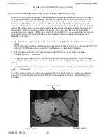
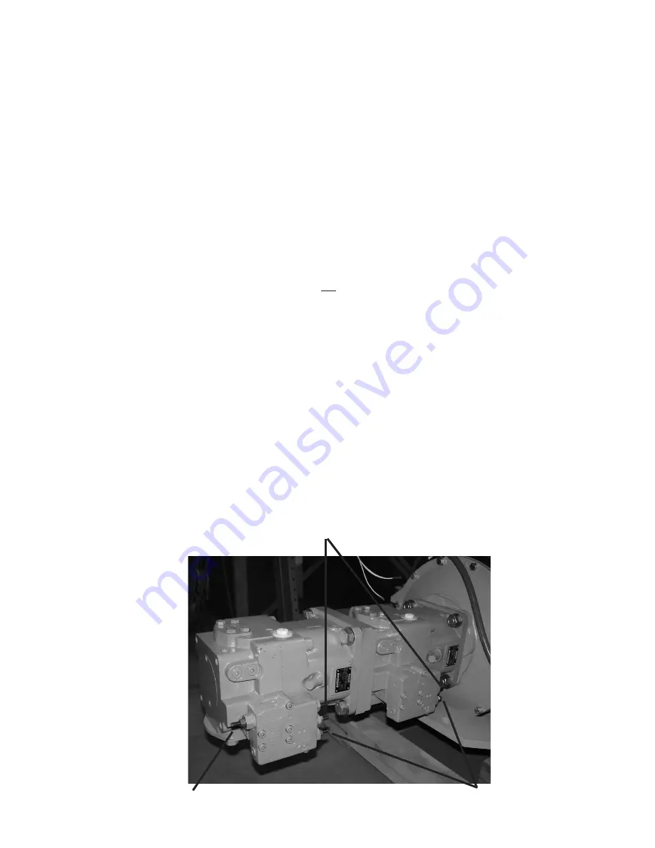
Standby pressure


Pump compensator 

Torque Control


1.  Install an electronic (digital) gauge on the system pressure test port (which is located on the main control   


valve).  


NOTE: When setting standby pressure, pressure will spike to approx. 3600 PSI before reading 425 PSI.  This  


will ruin a 1000 PSI gauge.  Use an electronic (digital) gauge to check standby pressure.


2.  With engine at low throttle, set standby pressure to 425 PSI (turn screw clockwise to increase,    


counterclockwise to  

decrease).


3.   To adjust pressure, loosen jam nut on pressure control block located on pump with 1/2" wrench.  Adjust  


pressure by turning screw in or out with a 5/32" allen wrench.  Retighten jam nut prior to taking pressure 

reading.


4.  Install a 5000 PSI gauge on the system pressure test port (located on the fire wall, or the PX port on the 

upper    

control valve).


5.  With engine at low throttle, bottom out the main boom (up) or stick boom (in or out) and set the system 

pressure on the compensator screw to 3600 PSI (turn screw clockwise to increase, counterclockwise to 

decrease).  

Summary of Contents for 495B SD

Page 1: ...operating and safety instructions for a Slasher Saw Attachment or Carrier Lower are not included in this manual See Slasher Saw or Carrier manufacturer s information NOTE The Grapple Service and Inst...

Page 2: ...2 HYDRAULIC DRAWING TANDEM 33 HYDRAULIC SERVO TANDEM 34 HYDRAULIC SCHEMATIC TANDEM 35 HYDRAULIC PRESSURE SETTINGS 495ML 36 MACHINE FUNCTION SPEEDS 36 HYDRAULIC PRESSURE ADJUSTMENTS 37 HYDRAULIC RESERV...

Page 3: ...Introduction...

Page 4: ...preventing some of the thousands of injuries and deaths caused by industrial accidents each year A professional operator should also be familiar with the information contained in other applicable sour...

Page 5: ...Ignition Key Switch Power On Accessory Power Off Power On Horn Starter Engine RPM Faster Slower Air Conditioner a c air conditioner AC Articulated Carrier Art Car adj adjust or adjusting appl applica...

Page 6: ...provide a fuse action to protect the machine and the operator from overloading When overloaded the machine can become stressed to a level where part fractures cause death se vere injury or property d...

Page 7: ......

Page 8: ...he machine being operated in an unsafe manner 6 Never use a boom or attachment for a work platform or personnel carrier Serious injury or death may result 7 When machine is not operating or when leavi...

Page 9: ...r bed is the owner s responsibility See Mounting Instructions for recommended procedures WARNING When using a Slasher Saw Attachment be sure to get proper safety and operating manuals from Slasher man...

Page 10: ...or s view re sulting in machine being operated in an unsafe manner Never use a boom attachment for a work platform or personnel carrier An unstable machine can cause death severe injury or property da...

Page 11: ...and steps when mounting or dismounting Never jump on or off machine Do not rush Walk do not run Mechanically connected controls will cause movement of components at all times even if pump or engine is...

Page 12: ...lt in death or severe injury This is a 12 volt negative ground electrical system Always wear seat belt when operating or running ma chine Check the Air Cleaner Assembly daily for cracks loose clamps o...

Page 13: ...oisture ice and snow affect the machine stability Irregular terrain must be traveled at slower speeds Direction of travel Avoid operating the machine across the slope When possible travel up or down s...

Page 14: ...train fuel system and hydraulic system Clean as often as necessary to help prevent overheating and combustion The electrical system battery electrical connections etc can be a source of arcs or sparks...

Page 15: ...08 31 2016 MODEL DESCRIPTION Hydraulic Oil Reservoir Shouding Power Unit Pumps Cab Stick Boom Cylinder Stick Boom Main Boom Cylinder Counterweight Exhaust Main Boom Head Assembly Platform Control Deck...

Page 16: ...Maintenance...

Page 17: ...not weld on any structural member unless specifi cally authorized by Barko Hydraulics Any unauthorized welding or welding procedures will void the warranty and may cause death severe injury property...

Page 18: ...nce procedure after the first 100 hours of operation 1 Do a complete inspection of the loader Rectify any problems replace any damaged parts 2 Check torque retorque if necessary Turntable Bearing Moun...

Page 19: ...Operation and Maintenance Manual 495B ML TM S 19 Last Updated 08 31 2016 SERVICE SCHEDULE...

Page 20: ...Operation and Maintenance Manual Last Updated 08 31 2016 495B ML TM S 20 SERVICE SCHEDULE CONTINUED...

Page 21: ...Operation and Maintenance Manual 495B ML TM S 21 Last Updated 08 31 2016 SERVICE SCHEDULE CONTINUED...

Page 22: ...Operation and Maintenance Manual Last Updated 08 31 2016 495B ML TM S 22 SERVICE SCHEDULE CONTINUED...

Page 23: ...Operation and Maintenance Manual 495B ML TM S 23 Last Updated 08 31 2016 SERVICE SCHEDULE CONTINUED...

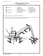
Page 24: ...Motor Gearboxes gear fluid see Swing Motor Gearbox Maintenance section in Service Manual approx 5 07 quarts 4 8 Liters if lube reservoir is used maintain it at half full LUBRICATION POINTS PERFORM DA...

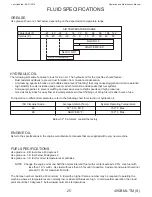
Page 25: ...High stability to resist oxidation and prevent varnish formation and deposits that foul systems Anti wear properties to prevent scuffing and exccesive wear at high speeds and high pressures Good visc...

Page 26: ...LTERNATIVE LUBRICANTS Conditions in certain geographical areas may require special lubricants and lubrication practices which do not appear in this manual LUBRICANT STORAGE The machine can operate at...

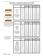
Page 27: ...ing Studs and Nuts 600 Ft Lbs 814 Nm Valve Bank Studs Nuts Tighten in a clockwise pattern so that all nuts are tightened equally without binding on the valve bank Final torque should be K170 valves 44...

Page 28: ...64 72 9 16 154 171 92 102 5 8 212 240 127 144 3 4 376 420 226 252 7 8 606 668 364 400 1 909 995 545 597 1 1 8 1288 1444 773 866 1 1 4 1817 2012 1090 1207 1 3 8 2382 2712 1430 1627 1 1 2 3161 3557 1897...

Page 29: ...Hydraulic...

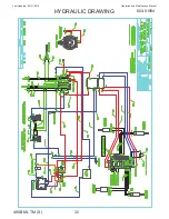
Page 30: ...Operation and Maintenance Manual Last Updated 08 31 2016 495B ML TM S 30 HYDRAULIC DRAWING 603 01594...

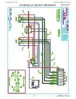
Page 31: ...Operation and Maintenance Manual 495B ML TM S 31 Last Updated 08 31 2016 HYDRAULIC SERVO DRAWING 603 01593...

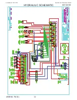
Page 32: ...Operation and Maintenance Manual Last Updated 08 31 2016 495B ML TM S 32 HYDRAULIC SCHEMATIC 607 00185...

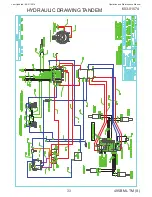
Page 33: ...Operation and Maintenance Manual 495B ML TM S 33 Last Updated 08 31 2016 HYDRAULIC DRAWING TANDEM 603 01574...

Page 34: ...Operation and Maintenance Manual Last Updated 08 31 2016 495B ML TM S 34 HYDRAULIC SERVO TANDEM 603 01573...

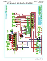
Page 35: ...Operation and Maintenance Manual 495B ML TM S 35 Last Updated 08 31 2016 HYDRAULIC SCHEMATIC TANDEM 607 00184...

Page 36: ...up butt end of main boom cylinder 4000 PSI 276 Bar at the Port Relief Main Boom down rod end of main boom cylinder 1800 PSI 124 Bar at the Port Relief Stick Boom up butt end of secondary boom cylinde...

Page 37: ...ase 3 To adjust pressure loosen jam nut on pressure control block located on pump with 1 2 wrench Adjust pressure by turning screw in or out with a 5 32 allen wrench Retighten jam nut prior to taking...

Page 38: ...the pump to keep dirt and dust out if cap is to tight it will add to system pressure Adjust pressures and reconnect hoses Repeat for other pump Standby pressure Pump compensator Torque Control 1 Insta...

Page 39: ...dby pressure to 425 PSI by turning screw in or out with a 5 32 allen wrench turn screw clockwise to increase counterclockwise to decrease 5 Tighten jam nut 6 Stall saw or plug pressure line 7 Run engi...

Page 40: ...1500 PSI Toadjust installagaugeontheloadsensetestportlocatedonthepump seePumpAdjustmentsforlocation of test port Remove the acorn nut and loosen the jam nut 13 mm wrench Using a 4 mm Allen wrench turn...

Page 41: ...educers To adjust the pressure install a gauge on the load sense test port located on the pump Adjust pressure at the load sense adjustment screw on the load sense relief on the valve bank inlet cover...

Page 42: ...ds tools funnels oil filling equipment the oil filler opening and above all the hydraulic oil itself must be kept absolutely clean Dirt in the hydraulic system can cause serious damage to pumps valves...

Page 43: ...Take new gasket from inside new element and install in groove in filter head 4 Apply oil to new gasket NOTE On a new machine the filter elements must be changed after the first 100 hours of operating...

Page 44: ...ervo filter has an indicator to show when filter needs servicing Check indicator daily to ensure proper service intervals CHANGING FILTER ELEMENT 1 Unscrew filter bowl from filter head 2 Replace old e...

Page 45: ...ow atmospheric pressure air may be drawn in where fluid will not necessarily leak out 5 Fluid level too low This can cause vortexing at pump inlet in reservoir thus drawing in air 6 Air trapped in fil...

Page 46: ...only creates aeration in the fluid but also provides the risk of contamination entering the fluid and components with the air The easiest way to effectively reduce and possibly eliminate this problem...

Page 47: ...worn or damaged replace them 8 Install new seals ensure order is as shown in diagram NOTE Special pliers part number 412 00409 can be used to aid in assembly see photo on next page Install item 10 be...

Page 48: ...RING 1 11 O RING 1 1 3 6 2 7 8 10 9 11 5 4 2 6 NOTE Follow order and orientation of seals shown in drawing Expansion ring on item 8 must point towards pressurized end of cylinder with item 10 behind...

Page 49: ...essure line disconnected cap off the load sense line that runs from the LSP port to port 4 on the collector a seal leak between the pressure port and load sense port will cause the pump to stay stroke...

Page 50: ...Collector 553 02044 See Figure 3 Find a clean work area to perform this procedure 1 Remove retaining plate cap screws retaining plate dust shield o ring and nylon thrust washer Separate the spool and...

Page 51: ...r the first back up o ring that you installed Do not stop during this process because the stretched seal will want to go back to its original shape making it more difficult to install without damage N...

Page 52: ...ressure on the spool until at least the second seal is inserted into the bore Using a plastic mallet gently and slowly tap the spool into the housing until it appears to be almost all the way home 15...

Page 53: ...rdered Holding tool for bushing can be ordered Bushing for 1 1 4 DIA can be ordered DISASSEMBLY REFER TO FIGURE 1 1 Remove parallel key item 8 from non splined shaft if used 2 Put motor in main holdin...

Page 54: ...s with hydraulic oil and grease rubber parts with vaseline REASSEMBLY 1 Place motor housing in main holding tool with flange uppermost Grease check valves item 11 check valves must have new o rings an...

Page 55: ...shaft journal on a 1 1 4 splined shaft 15 Turn gearwheel set counterclockwise until cardan shaft and gearwheel start to mesh 15 degrees See Figure 2 16 Turn gearwheel rim so that holes made for screws...

Page 56: ...r filler plug located in the top of the oil expansion tank See Figure 1 If a lube reservoir is used keep adding fluid to the lube reservoir until gearbox is full and lube reservoir remains at half ful...

Page 57: ...Electrical...

Page 58: ...Operation and Maintenance Manual Last Updated 08 31 2016 495B ML TM S 58 ELECTRICAL SCHEMATIC...

Page 59: ...Operation and Maintenance Manual 495B ML TM S 59 Last Updated 08 31 2016 ELECTRIC DRAWING SERVO...

Page 60: ...belt adjustment see ALTERNATOR DRIVE BELT ADJUSTMENT information Loose wire connections Be sure all wires are tightly connected Broken or open wires Replace any wires that are damaged or worn Proper e...

Page 61: ...first jumper cable to positive terminal of extra battery Connect other end of same jumper cable to positive terminal of machine battery 6 Connect end of second jumper cable to negative terminal of ex...

Page 62: ...nals with any metal Sparks may occur causing damage to battery and personal injury ALTERNATOR DRIVE BELT ADJUSTMENT 1 Loosen alternator adjusting bolt and mounting bolt See Figure 1 2 Move alternator...

Page 63: ...l engine RPM 6 The ammeter reading must be within 10 percent of rated amperage marked on alternator case 7 If reading is correct alternator is good If reading is more or less than 10 percent of rated...

Page 64: ...s loose or damaged 2 Battery connections are dirty of loose 3 Battery is damaged 4 The ground connection is not making a good contact 5 The alternator is damaged 6 The engine is locked 7 The starter h...

Page 65: ...act at all times between the brush and the brass ring and is especially important if an orbiting condition develops as the equipment ages COLLECTOR MAINTENANCE Under normal operating conditions the se...

Page 66: ...5 amp brush arm spring assemblies Because of their small size they can be broken if forced up or down In the correctly installed position the possibility of breakage is minimal LUBRICATION Electric co...

Page 67: ...ociety MACS and the National Institute for Automotive Service Excellence ASE are approved by the Environmental Protection Agency EPA as organizations with approved independent testing and certificatio...

Page 68: ...mperatures 8 10f CONDENSER temperatures are not ambient temperatures Add to ambient 35 40 F for proper heat transfer then refer to pressure chart Example 90 F ambient temp 40 Conditions will vary for...

Page 69: ...Operation and Maintenance Manual 495B ML TM S 69 Last Updated 08 31 2016 AIR CONDITIONER MAINTENANCE CONTINUED Barko Magnum Plus Series...

Page 70: ...Operation and Maintenance Manual Last Updated 08 31 2016 495B ML TM S 70 AIR CONDITIONER MAINTENANCE CONTINUED 72 87 5 520 5 72 86 72 87 6 6 3 5 7 8675 7 21...

Page 71: ...Operation and Maintenance Manual 495B ML TM S 71 Last Updated 08 31 2016 AIR CONDITIONER MAINTENANCE CONTINUED...

Page 72: ...Operation and Maintenance Manual Last Updated 08 31 2016 495B ML TM S 72 AIR CONDITIONER MAINTENANCE CONTINUED...

Page 73: ...Operation and Maintenance Manual 495B ML TM S 73 Last Updated 08 31 2016 AIR CONDITIONER MAINTENANCE CONTINUED...

Page 74: ...Operation and Maintenance Manual Last Updated 08 31 2016 495B ML TM S 74 AIR CONDITIONER MAINTENANCE CONTINUED...

Page 75: ...Operation and Maintenance Manual 495B ML TM S 75 Last Updated 08 31 2016 AIR CONDITIONER MAINTENANCE CONTINUED 1 2 3 4 5 6 2 7 8...

Page 76: ...Manual Last Updated 08 31 2016 495B ML TM S 76 AIR CONDITIONER MAINTENANCE CONTINUED LDJQRVLQJ DQ SDQVLRQ 9DOYH 6 VWHP RZ 6LGH LJK 6LGH 6LJKW ODVV YDSRUDWRU 2XWOHW XFW 7HPSHUDWXUH RZ 6LGH LJK 6LGH 6...

Page 77: ...4 9 8 5 5 85 29 4 94 9 91 8 25 31 7 6 9 2 3 90 32 2 103 9 99 8 20 28 9 3 7 0 6 95 35 0 113 5 108 3 15 26 1 0 0 2 4 100 37 8 123 6 117 2 10 23 3 1 9 4 5 105 40 6 134 3 126 6 5 20 6 4 1 6 7 110 43 3 145...

Page 78: ...Maintenance...

Page 79: ...chine is a Cummins diesel engine Complete specifications operating instructions and maintenance and lubrication information will be found in the engine manufacturer s manuals which ship with the machi...

Page 80: ...hecked daily at the same time checking for fluid leaks Because the lubricant system is the heart of the unit it is especially important that the fluid be kept clean The following procedures should be...

Page 81: ...ing pocket 6 After all driven gears and their bearings have been removed position gear box so that the engine adaptor is facing up Remove place bolts and lift engine adaptor up from gear box Lift pini...

Page 82: ...l On flywheel housings involving more than 4 bolt holes be sure cord gasket lap joint falls behind one hole location which will be used for a bolt or stud fastener Do not lap ends behind an unused bol...

Page 83: ...and turn adjusting yoke to right or clockwise until operating lever requires a distinct pressure to engage A new clutch requires several adjustments until friction discs are worn in See Figure 5 For...

Page 84: ...ENGINE DAMAGE IS DUE TO CARELESS SERVICE PROCEDURES By following the steps shown below and on the next few pages you can avoid unnecessary dust contamination to the engine The following steps should...

Page 85: ...ON INDICATORS Measure the restriction of the Air Cleaner with a service gauge or a water manometer at the restriction tap provided in the Air Cleaner the transfer pipe or the blower intake Replace the...

Page 86: ...element was not firmly sealed or that a dust leak exists Make certain the cause of that leak isidentifiedandrectifiedbeforereplacingthe element 5 PRESS YOUR FRESH GASKET TO SEE IF IT SPRINGS BACK Make...

Page 87: ...to your engine If the element is not going to be changed and reassembled immediately cover the opening The only way to be sure nothing got in is to be sure nothing gets in THE IMPORTANT DON TS TO ALW...

Page 88: ...Operation and Maintenance Manual Last Updated 08 31 2016 495B ML TM S 88 Structural...

Page 89: ...ve power noise a steady increase of bearing clearance which accelerates towards the end of the bearing life The last item bearing clearance can be measured and is a good means of determining the beari...

Page 90: ...Figure 1 Set dial indicator 4 Balance the machine so as to have zero moment load on the bearing This is done by adjusting the boom angle Zero moment is when the upper race is at its lowest position a...

Page 91: ...75 087 094 110 114 118 122 90 079 091 098 114 118 122 126 100 079 091 102 114 122 124 126 110 094 102 118 126 128 130 120 098 106 122 126 130 134 130 102 110 126 130 134 138 140 114 126 134 136 138 15...

Page 92: ...nance Manual Last Updated 08 31 2016 495B ML TM S 92 87 2 3 1 5 7 1 5 1 1 83 220 685 7 5 1 5 67 3 87 2 3 1 5 7 1 5 67 3 21 86 2 7 72 17 5 3 1 5 7 1 5 29 5 2 67 3 33 17 6 72 167 6 6 2 1 72548 72 7 6 LI...

Page 93: ...anual 495B ML TM S 93 Last Updated 08 31 2016 ITEM QTY PART NO DESCRIPTION 1 1 113 01529 PL PIN LOCK 3 125 HEX 2 1 482 00256 BOLT 2 12UNX10 5 DGP 3 1 514 00096 WASHER 2 DIA X 4 OD X 1 4 THICK 4 1 513...

Page 94: ...s section of machine s Operator s Manual Loose or overtorqued bolts can cause death severe injury or property damage Maintain proper bolt torque Visually check bolts daily Check torque every 100 hours...

Page 95: ...Trouble Shooting...

Page 96: ...for and repair any leaks Drain engine oil and fill with heavier weight engine oil Engine overheats Low coolant level Loose worn or broken fan belt Radiator plugged Air filter elements plugged Fill to...

Page 97: ...hydraulic oil viscosity Excessive load Pump not receiving hydraulic oil Damaged line Any or all of the following Replace dirty filters Clogged inlet line Clean reservoir breather vent Fill reservoir...

Page 98: ...rong engine oil Clean and tighten connections Replace engine oil Refer to Fuel and Lubricants Gauges do not work Gauge sender needs service Loose gauge ground connection Replace sender Check ground co...

Page 99: ...tem Carrier system not operational Repair or replace sources of leaks and blocks Repair or replace as needed Machine steering in opposite direction if applicable Lines to cylinders connected to wrong...

Page 100: ...need 133 00708 INSTALL DRAWING subframe non skid mat l 1 163 01115 INSTALL DRAWING platform non skid mat l 1 539 00868 NON SKID MATERIAL 6 wide AR 539 00950 NON SKID MATERIAL 12 wide AR NOTE This sec...

Page 101: ...1 Banks Avenue Superior WI 54880 phone 715 395 6700 fax 800 772 2448 website www barko com email parts barko com...

Reviews: