Operation and Maintenance Manual
495B ML TM (S)
41
Last Updated - 08/31/2016
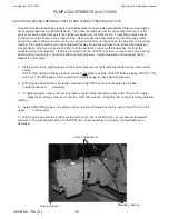
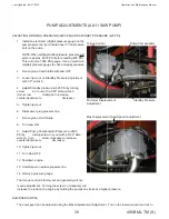
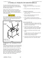
HYDRAULIC PRESSURE ADJUSTMENT CONTINUED...
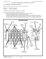
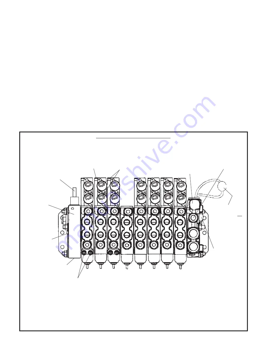
L90 LOWER VALVE BANK ADJUSTMENTS (558-01627)
Sections with Feed Reducers:
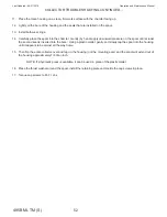
Sections 1 and 3 are equipped with adjustable feed reducers to control pressure. When making adjustments on
the feed reducers, install a gauge on the load sense test port located on the pump. These feed reducers are pre-
set to 1800 PSI. To decrease the pressure, remove the plastic caps on the feed reducers, loosen the lock nut with
a 10 mm wrench and turn the adjustment screw out (counterclockwise) with a 3 mm Allen wrench.
Sections without Feed Reducers:
To adjust the pressure, install a gauge on the load sense test port located on the pump. Adjust pressure at the
load sense adjustment screw on the load sense relief on the valve bank inlet cover. Pressure should be 2800 PSI.
L90 LOWER VALVE BANK 558-01627
Bar Up
Saw
Saw
Knives
Stab
Stab
Stab
Stab
Solenoids (qty 14)
Feed Reducers
(2 per section on sections
1 and 3 only)
(A on left, B on right)
Outlet
Cover
Pump
Pressure Port
(PX)
Load Sense
Pressure Port
(PL)
B
A
B
A
B
A
B
A
B
A
B
A
B
A
B
A
B
A
B
A
B
A
B
A
B
A
B
A
B
A
Pilot Relief
(pressure
reducing
valve)
B
A
1
2
3
4
5
6
7
8
B-Port Electric End Caps (qty 7)
Load Sense Relief
Inlet
Cover
Pilot Filter:
On this valve bank
the Pilot Filter is not
incorporated into
the valve bank but
is a separate filter,
565-01255, and not
shown here.
Drain to
port TP
L90 LOWER VALVE BANK ADJUSTMENTS
Summary of Contents for 495B SD
Page 3: ...Introduction...
Page 7: ......
Page 16: ...Maintenance...
Page 19: ...Operation and Maintenance Manual 495B ML TM S 19 Last Updated 08 31 2016 SERVICE SCHEDULE...
Page 29: ...Hydraulic...
Page 57: ...Electrical...
Page 58: ...Operation and Maintenance Manual Last Updated 08 31 2016 495B ML TM S 58 ELECTRICAL SCHEMATIC...
Page 78: ...Maintenance...
Page 88: ...Operation and Maintenance Manual Last Updated 08 31 2016 495B ML TM S 88 Structural...
Page 95: ...Trouble Shooting...


