


Operation and Maintenance Manual
495B ML TM (S)
89
Last Updated - 08/31/2016
Structural
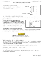
TURNTABLE BEARING MAINTENANCE
The turntable bearing area is a potential pinch point. Before doing any
maintenance or inspection on turntable bearing, lower boom and attachment
to the ground, shut machine down to a zero energy state and put ignition
key in your pocket.
GENERAL
Large diameter bearings are designed and manufactured with a certain clearance in order to obtain smooth rotation
with low drive torque requirements.
The design clearance will be increased minimally after the bearing is subjected to a load and after hours of operation
smooth down the raceway surface. After this initial “break-in” period, the bearing will remain essentially constant for
many years if proper maintenance is performed.
SIGNS OF A WORN OUT BEARING
A bearing that is wearing out will begin to show pitting in the contact area of the raceway. At this state, the bearing
is still functionally acceptable, since the initial number of pittings is very small and usually multiplies at a low rate.
Eventually the number of pittings increases to a density where material particles are spalled out of the raceway
and the bearing finally becomes non-functional, worn out. The following signs will show up if a bearing is pitting or
spalling:
- small metal particles in the grease.
- operation changes from smooth to rough.
- an increase in necessary drive power.
- noise.
- a steady increase of bearing clearance which accelerates towards the end of the bearing life.
The last item, bearing clearance, can be measured, and is a good means of determining the bearing condition.
MEASURING BEARING CLEARANCE
Permissable bearing clearance differs between bearing types. See Table 1 for guidelines. Note that the values given
are allowable differentials between the no-wear and maximum allowable wear condition of the bearing. So in order for
the Tables to apply, bearing clearance must be measured right after equipment assembly, and at intervals thereafter,
using the same points of reference each time. If the clearance has not been measured at assembly, additional
clearance values have to be added considering design clearance of the bearing deflection for the bearing under load,
and deflection of the mounting structure. The latter may be influenced considerably by positioning of the dial indicator
which, as a rule, should be as close to the bearing raceways as possible.
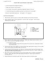
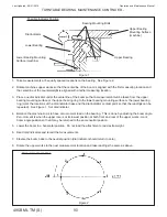
MEASURING PROCEDURE
Position the dial indicator(s) as close as possible to the outer edge of the bearing. Figure 1 shows indicator position
for one type of mounting arrangement.
Consecutive measurements must be taken in the same positions and with the same load as the initial measurement.
If the maximum permissable clearance is reached at any measurement position, bearing removal, disassembly and
inspection must be performed. Call the factory with any questions.
Do not operate machine with a bearing that is worn out, damaged or
has reached maximum permissable clearance measurements. Death,
Summary of Contents for 495B SD
Page 3: ...Introduction...
Page 7: ......
Page 16: ...Maintenance...
Page 19: ...Operation and Maintenance Manual 495B ML TM S 19 Last Updated 08 31 2016 SERVICE SCHEDULE...
Page 29: ...Hydraulic...
Page 57: ...Electrical...
Page 58: ...Operation and Maintenance Manual Last Updated 08 31 2016 495B ML TM S 58 ELECTRICAL SCHEMATIC...
Page 78: ...Maintenance...
Page 88: ...Operation and Maintenance Manual Last Updated 08 31 2016 495B ML TM S 88 Structural...
Page 95: ...Trouble Shooting...


