page 29
595 ML CRL (S)
800-00177
HYDRAULIC PRESSURE ADJUSTMENT
(AA11V-095-095)
ADJUSTING TRACK PRESSURE (4500 PSI) AND STANDBY PRESSURE (425 PSI)
Note: When setting the track pressure and standby pressure on a double pump system the two pumps must be
set at equal pressures for optimal efficiency. The pressure readings from the pump output test port, or the
system pressure output test port is the highest pressure from the either pump. To set both pumps equally,
increase one of the blocks to the proper setting. Now increase the other block such that the gauge reads
above the proper setting to ensure it is the one giving the reading, now back down the pressure to the proper
reading.
If the proper setting can not be obtained this way the pumps will have to be isolated and adjusted
independently. Remove one pump at a time from the system by removing the load sense line from the
opposite pump to be adjusted. Tighten a JIC plug to the tee, LOOSELY screw on a cap to the pump to keep
dirt and dust out (if cap is to tight it will add to system pressure). Adjust pressures and reconnect hoses.
Repeat for other pump.
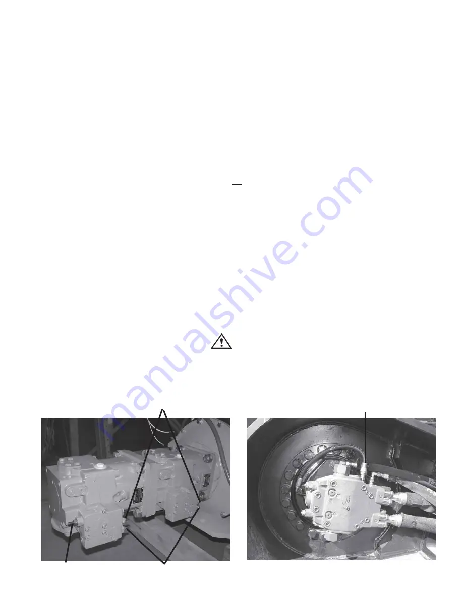
Standby pressure
Brake Line
Torque Control
1.
Install an electronic (digital) gauge on the system pressure test port (which is located on the main control valve).
NOTE: When setting standby pressure, pressure will spike to approx. 4500 PSI before reading 425 PSI. This
will ruin a 1000 PSI gauge. Use an electronic (digital) gauge to check standby pressure.
2.
With engine at low throttle, set standby pressure to 425 PSI (turn screw clockwise to increase,
counterclockwise to decrease).
3.
To adjust pressure, loosen jam nut on pressure control block located on pump with 1/2" wrench. Adjust
pressure by turning screw in or out with a 5/32" allen wrench. Retighten jam nut prior to taking pressure reading.
4.
To set track pressure install a 5000 PSI gauge on the system pressure test port (located on the fire wall, or the
PX port on the upper control valve).
5.
With machine off disconnect brake line from left track, plug port and cap line (see photo). This will allow
pressure to be applied to the left track motor without moving the machine, the brake will stay engaged.
6.
With engine at low throttle, press left foot pedal all the way forward and set the track pressure on the
compensator screw to 4500 PSI (turn screw clockwise to increase, counterclockwise to decrease).
WARNING
With left track brake line disconnected right track can still
move causing property damage, severe injury, or death.
The torque control is factory set and generally will not require adjustment. Turning the screw in (clockwise) will
increase the load on the engine by holding the pumps on stroke at a higher pressure.
Pump compensator
Summary of Contents for 595ML
Page 3: ...page3 595 ML CRL S 800 00177 Introduction Marker...
Page 16: ...page16 595 ML CRL S 800 00177 Maintenance A PREVENTIVE MAINTENANCE Maintenance...
Page 27: ...page27 595 ML CRL S 800 00177 Maintenance B HYDRAULIC SYSTEM...
Page 33: ...page33 595 ML CRL S 800 00177 HYDRAULIC PRESSURE ADJUSTMENT CONTINUED 558 01699...
Page 44: ...page44 595 ML CRL S 800 00177 Maintenance C ELECTRICAL SYSTEM MAINTENANCE...
Page 67: ...page67 595 ML CRL S 800 00177 Maintenance D POWER UNIT MAINTENANCE...
Page 77: ...page77 595 ML CRL S 800 00177 Structural E STRUCTURAL MAINTENANCE...
Page 84: ...page84 595 ML CRL S 800 00177 Trouble Shooting Marker Marker Marker...


