page 30
595 ML CRL (S)
800-00177
Standby pressure
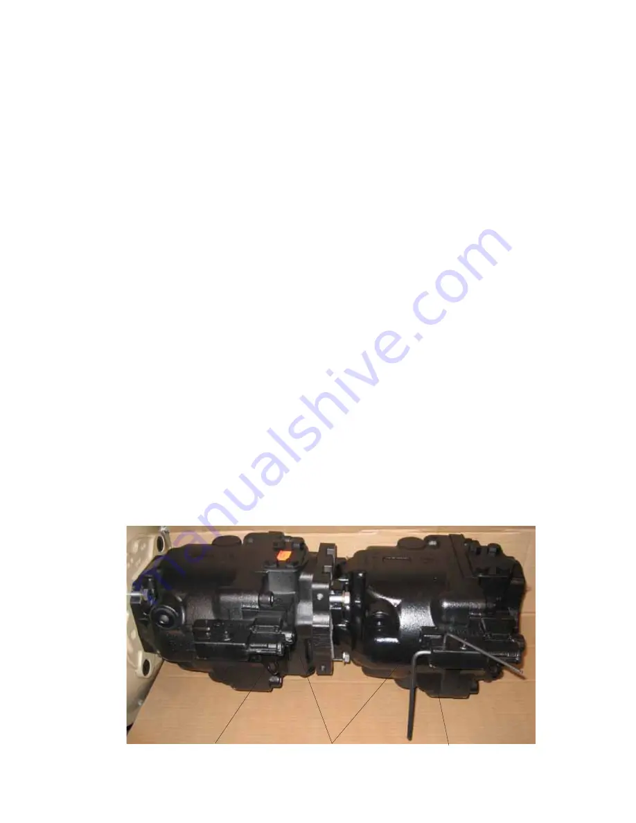
Pump
compensator
Standby pressure
PUMP ADJUSTMENT CRL (SAUER TANDEM)
(SAUER - SERIES 45 - 100/100)
1.
Pressure adjustments at the pump control the track drive; all other functions are controlled by the load sense
manifold.
2.
Install an electronic gauge on the PX system pressure test port located on the bulkhead to the right of the
hydraulic pumps.
Note; When setting standby pressure, pressure will spike to 3000 psi. before dropping back to standby
settings. This will ruin a 1000 psi gauge; to adjust pressure correctly an electronic gauge is recommended
3.
Disconnect brake line from left track, plug port and cap line (see photo). This will allow pressure to be applied
to the left track motor without causing movement of the loader. This will enable you to bring the pump up to
pressure to properly set pump to 4500 psi.
4.
With electronic gauge on the PX test port, start engine to check and adjust standby pressure. When reading
the gauge with the dual pump system keep in mind that the gauge will read the highest pressure of the two
pumps. To make sure both pumps are equal adjust one of the standby adjustment screws in until the pressure
starts to rise. (See photo for proper adjustment screw, a #4 metric Allen wrench is required to loosen set screw
and a # 6 Allen wrench is required to make the pressure adjustment). Turn screw in (clockwise) to raise or out
to lower (counter clockwise). If you are unable to set the pressure to 425 psi, it may be necessary to lower the
adjustment on the other pump. Once you have pump set to 425 psi. repeat the procedure for the second pump.
5.
With the electronic gauge on the PX test port and the brake line removed gently stroke the travel pedal on the
left track to bring the pumps up to pressure. Keep in mind that the electronic gauge will read the highest
pressure of the two pumps. To make sure both pumps are equal raise one of the pressure compensator
adjustments (See photos for proper adjustment screw) in (clockwise) until pressure is at the factory
recommended 4500 psi. If pressure reads high, it may be necessary to lower the second pump to enable you
to set the pump to 4500 psi. Once your first pump is set, repeat the procedure for the second pump.
If at any time you have a problem setting the dual pump system properly you can separate the load sense lines
and set each pump independently. To do this remove the load sense line from the opposite pump that you want to
adjust, install a JIC plug on the load sense line and a JIC cap on the pump control. NOTE; be sure and leave the
JIC cap loose on the pump control or it will build up pressure and effect the pump you are adjusting. Once you have
load sense lines properly disconnected you can adjust that pump independently, reverse procedure for the
second pump.
Summary of Contents for 595ML
Page 3: ...page3 595 ML CRL S 800 00177 Introduction Marker...
Page 16: ...page16 595 ML CRL S 800 00177 Maintenance A PREVENTIVE MAINTENANCE Maintenance...
Page 27: ...page27 595 ML CRL S 800 00177 Maintenance B HYDRAULIC SYSTEM...
Page 33: ...page33 595 ML CRL S 800 00177 HYDRAULIC PRESSURE ADJUSTMENT CONTINUED 558 01699...
Page 44: ...page44 595 ML CRL S 800 00177 Maintenance C ELECTRICAL SYSTEM MAINTENANCE...
Page 67: ...page67 595 ML CRL S 800 00177 Maintenance D POWER UNIT MAINTENANCE...
Page 77: ...page77 595 ML CRL S 800 00177 Structural E STRUCTURAL MAINTENANCE...
Page 84: ...page84 595 ML CRL S 800 00177 Trouble Shooting Marker Marker Marker...


